While Boolean logic is very important when writing computer code, it is also a major part of working with computer hardware as well. In fact, most electronic hardware today uses chips and circuits that are built directly upon the fundamental building blocks of Boolean logic.
Relay and Switching Circuits
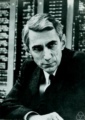
In 1937, a 21-year-old graduate student at MIT named Claude Shannon, pictured above, published his master’s thesis: “A Symbolic Analysis of Relay and Switching Circuits.” In that paper, he demonstrated how to build electric circuits which could perform all of the standard Boolean logic operations, using the presence or absence of an electric current or voltage to represent true and false in those circuits.
In addition, his work demonstrated that multiple circuits can be combined to perform simple mathematical operations on binary numbers, such as addition, subtraction, and even multiplication!
It is difficult to overstate the importance of Claude Shannon’s work in today’s modern world. Every electronic device we use is built upon the same fundamental concepts laid out by Shannon in the 1930s. In fact, one researcher described his work as “possibly the most important, and also the most famous, master’s thesis of the century.”2
Addition using Boolean Logic
Let’s look at an example of how Boolean logic can be used to perform mathematical operations. Here is a simple truth table showing addition using two binary bits as input. In this case,
$ 0 $ represents false and
$ 1 $ represents true:
| A | B | Carry (and) | Sum (xor) |
|---|---|---|---|
| 0 | 0 | 0 | 0 |
| 0 | 1 | 0 | 1 |
| 1 | 0 | 0 | 1 |
| 1 | 1 | 1 | 0 |
The addition itself is performed by the xor operation. For example, if both inputs are
$ 0 $, representing false, then the sum is
$ 0 + 0 = 0 $, which is false as well. However, if one input is
$ 1 $ and the other is
$ 0 $, then the sum is
$ 0 + 1 = 1 $ (which is the same as
$ 1 + 0 = 0 $), so the xor operation would output true. In both of those cases, the carry bit is
$ 0 $, since the sum does not require a bit to be carried forward to the left.
The interesting case is when both inputs are
$ 1 $. In this case, the result is
$ 1 + 1 = 2 $, where
$ 2 $ is represented by
$ 10 $ in binary. So, the sum result, represented by xor is false, but the carry bit, represented by the and operation, is true. So, the result would be
$ 10 $, represented by the carry bit followed by the sum.
So, we can represent the mathematical addition operation $ A + B $ using these two Boolean logic expressions:
- Sum: $ A \oplus B $
- Carry: $ A \land B $
The corresponding circuit for this operation is known as a half adder.
We can then expand this truth table to include a third input, which is the carry bit from a previous addition.
| A | B | Carry In | Carry Out | Sum |
|---|---|---|---|---|
| 0 | 0 | 0 | 0 | 0 |
| 0 | 0 | 1 | 0 | 1 |
| 0 | 1 | 0 | 0 | 1 |
| 0 | 1 | 1 | 1 | 0 |
| 1 | 0 | 0 | 0 | 1 |
| 1 | 0 | 1 | 1 | 0 |
| 1 | 1 | 0 | 1 | 0 |
| 1 | 1 | 1 | 1 | 1 |
From this truth table, we can find the following Boolean logic expressions for the sum and carry bits:
- Sum: $ (A \oplus B) \oplus C $
- Carry: $ (A \land B) \lor (B \land C) \lor (A \land C) $
This circuit is known as a full adder.
So, given two binary bits as inputs $ A $ and $ B $, along with the carry bit from a previous addition $ C $, we can use these two Boolean expressions to find both the sum and carry bits as output.
To find the sum of larger numbers, we can simply chain together multiple instances of these full adder circuits together, moving through the binary number from left to right, just like we do for normal addition. In modern computers, the central processing unit, or CPU, contains circuits very similar to these to perform each mathematical instruction required to execute a program.
Wikibooks has a great page dedicated to this topic for additional information: Practical Electronics/Adders
-
File:ClaudeShannon MFO3807.jpg. (2018, December 28). Wikimedia Commons, the free media repository. Retrieved 19:09, January 14, 2019 from https://commons.wikimedia.org/w/index.php?title=File:ClaudeShannon_MFO3807.jpg&oldid=332553066. ↩︎
-
See https://en.wikipedia.org/wiki/A_Symbolic_Analysis_of_Relay_and_Switching_Circuits#cite_note-2 ↩︎