Chapter 3
Boolean Logic
Computing True and False or Not
Computing True and False or Not
In this chapter, we’re going to step away from computer programming for a bit to discuss a more foundational topic: logic. Logic and reasoning are core concepts at the heart of any level of education, and they are one of the major ways we are able to understand the world around us. Without logic and reasoning, we cannot build upon information we learn to create deeper meaning. Instead, all we are left with are facts, without any knowledge or wisdom gained from them.
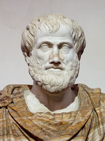
The earliest approach to formal logic comes from the work of Aristotle, seen above. His work established rules by which further information could be inferred, or deduced, from a set of truths about the world known as premises.
For example, in Aristotelian logic, we might find the following premises to be true:
Socrates is a man All men are mortal
Using Aristotle’s rules for logic, we can infer from those premises the following conclusion:
Socrates is mortal
This becomes a powerful system for inferring additional information based on facts in the world. By supporting each conclusion with premises and rules, it is possible to build a great wealth of knowledge.
In the 1800s, there was a great interest in using the rules of mathematics to understand the world as well. Mathematics contains a well understood set of rules and operations, and many thinkers hoped to find a way to apply those rules in the world of logic as well. By doing so, they could move away from using an imprecise spoken language to reason about the world, and instead use the very precise language of mathematics.
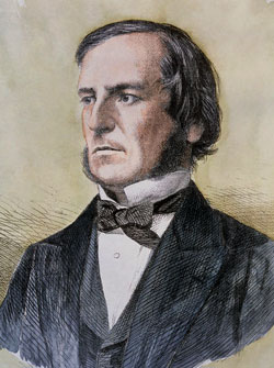
In 1854, George Boole, seen above, published An Investigation of the Laws of Thought on Which are Founded the Mathematical Theories of Logic and Probabilities, a book which described exactly how to combine mathematics and logic into a single system. Using the system he proposed, it became very easy to use mathematical expressions and rules to perform the same logical inferences that Aristotle first used nearly 2000 years prior.
In Boolean logic, we may understand the following premises to be true:
$$ A \land B $$ $$ B \land C $$
In this instance, the $ \land $ symbol is used to denote the word “and”. We’ll learn more about these symbols later in this chapter. Using a rule from Boolean logic, we can reach the following conclusion:
$$ A \land C $$If we compare the example from Aristotelian logic above to this example from Boolean logic, we can quickly see that they are very similar in structure. The first premise establishes a relationship between two items. The second premise establishes another relationship between the second item in the first premise, and a third item. The conclusion states that there must be a relationship between the first and third items. This is very similar to the transitive property of some mathematical operators.3
In programming, we use Boolean logic to control many aspects of how our computer programs function. In this chapter, we’ll learn all about how Boolean logic works so we can apply it correctly in our programs.
File:Aristotle Altemps Inv8575.jpg. (2018, November 23). Wikimedia Commons, the free media repository. Retrieved 20:49, January 9, 2019 from https://commons.wikimedia.org/w/index.php?title=File:Aristotle_Altemps_Inv8575.jpg&oldid=328967130. ↩︎
File:George Boole color.jpg. (2018, November 19). Wikimedia Commons, the free media repository. Retrieved 21:02, January 9, 2019 from https://commons.wikimedia.org/w/index.php?title=File:George_Boole_color.jpg&oldid=328260467. ↩︎
This is not a perfect translation from Aristotelian logic to Boolean logic, but it fits well within the scope of this textbook. A more appropriate translation would use implication ( $ \implies $), but we won’t be using that concept, so it has been substituted with “and” instead. ↩︎
Boolean logic contains four operators that perform various actions in a Boolean logic statement. Before we learn about them, let’s take a minute to discuss variables in Boolean logic.
As we covered in a previous chapter, most programming languages support a special data type for storing Boolean values. That data type can only contain one of two values, True or False. So, in a Boolean logic statement, any variable can only be either True or False
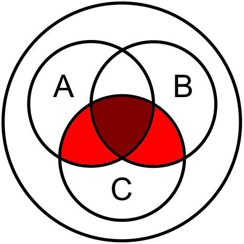
For each of the operators below, we’ll see both a truth table and Venn diagram representation of the operation. They both present the same information, but in a slightly different way. In each operation, we’ll see all possible values of the variables present in the statement, and the resulting value of the operation on those variables. Since each variable can only have two values, the possibilities are limited enough that we can show all of them.
In the Venn diagrams below, each circle represents a variable.1 The variables are labeled in the circles on each diagram.
The first, and simplest, Boolean logic operator is the not, or negation, operator. This operator simply negates the given Boolean value, turning True into False and False into True. When written, we use the
$ \neg $ symbol, but most programming languages use an exclamation point ! instead.
Below is a truth table giving the value of $ \neg A $ and $ \neg B $, for all possible values of $ A $ and $ B $.
| $ A $ | $ B $ | $ \neg A $ | $ \neg B $ |
|---|---|---|---|
| F | F | T | T |
| F | T | T | F |
| T | F | F | T |
| T | T | F | F |
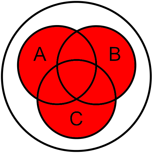
We can also see the operation visually using a Venn diagram. In these drawings, assume each individual variable is True, and the shaded portion shows which parts of the diagram are True for the entire statement.
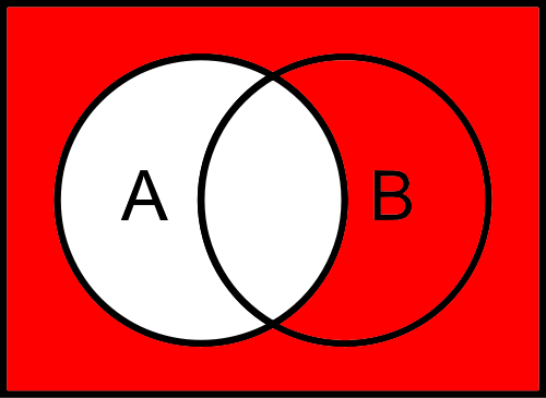
As we can see, if $ A $ is true, then $ \neg A $ represents everything in the diagram outside of the circle labeled $ A $. In fact, it includes the area outside of any circle, which represents the whole universe of items that are neither inside of $ A $ nor $ B $. So, the value of $ \neg A $ is not affected by the value of $ B $ in this instance.
We can also extend this to three variables, as shown in the truth table below. It gives the values of $ \neg A $, $ \neg B $, and $ \neg C $ for all possible values of $ A $, $ B $, and $ C $.
| $ A $ | $ B $ | $ C $ | $ \neg A $ | $ \neg B $ | $ \neg C $ |
|---|---|---|---|---|---|
| F | F | F | T | T | T |
| F | F | T | T | T | F |
| F | T | F | T | F | T |
| F | T | T | T | F | F |
| T | F | F | F | T | T |
| T | F | T | F | T | F |
| T | T | F | F | F | T |
| T | T | T | F | F | F |
The Venn diagram for this instance is very similar:
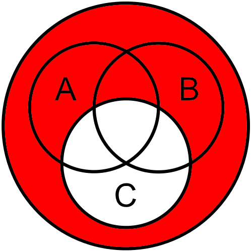
As we can see, the not operation is very useful when dealing with Boolean values.
The next Boolean logic operator we’ll cover is the and, or conjunction, operator. This operator works similar to the way we use “and” in our spoken language. If
$ A $ is True, while
$ B $ is also True, then we can say that both
$ A $ and
$ B $ are True. This would be written as
$ A \land B $. Most programming languages use two ampersands && to represent the Boolean and operator, but some languages also include and as a keyword to denote this operator.
Here is a truth table giving the value of $ A \land B $ for all possible values of $ A $ and $ B $.
| $ A $ | $ B $ | $ A \land B $ |
|---|---|---|
| F | F | F |
| F | T | F |
| T | F | F |
| T | T | T |
As we can see, the only time that
$ A \land B $ is True is when both
$ A $ and
$ B $ are True.
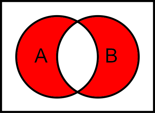
Next, we can look at a Venn Diagram that represents this operation
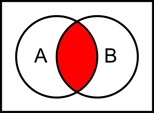
As we can see, only the center of the Venn diagram is shaded, representing the parts of the diagram that are both in $ A $ and $ B $ at the same time.
This operation also easily extends to three variables. This truth table gives the value of $ A \land B \land C $ for all possible values of $ A $, $ B $, and $ C $.
| $ A $ | $ B $ | $ C $ | $ A \land B \land C $ |
|---|---|---|---|
| F | F | F | F |
| F | F | T | F |
| F | T | F | F |
| F | T | T | F |
| T | F | F | F |
| T | F | T | F |
| T | T | F | F |
| T | T | T | T |
The Venn diagram for this instance is very similar to the one above:

Once again, we see that only the very center of the diagram is shaded, as expected.
The third Boolean operator is the or, or disjunction, operator. It is somewhat similar to how we use the word “or” in our spoken language, with a major difference. This operator would be written as
$ A \lor B $. Most programming languages use two vertical pipes || to represent the Boolean or operator, but some languages also include or as a keyword to denote this operator.
Consider ordering food at a restaurant as an example. On the menu, you might see the statement “Soup or Salad” as one of the options for your meal. This means that you must choose either “soup” or “salad” to go with your meal, but usually you aren’t allowed to have both (at least, without paying more).
Now, consider a similar statement,
$ A \lor B $. If either
$ A $ or
$ B $ are True, we would say that
$ A \lor B $ is also True. However, if both
$ A $ and
$ B $ are True, we would also say that
$ A \lor B $ is True. So, the Boolean or operator will return True when both inputs are True, which differs from how we use it in spoken language.
Here is a truth table giving the value of $ A \lor B $ for all possible values of $ A $ and $ B $.
| $ A $ | $ B $ | $ A \lor B $ |
|---|---|---|
| F | F | F |
| F | T | T |
| T | F | T |
| T | T | T |
As we can see, the only time that
$ A \lor B $ is False is when both
$ A $ and
$ B $ are False. As long as at least one of the values is True, the whole statement is True.
Next, we can look at a Venn Diagram that represents this operation
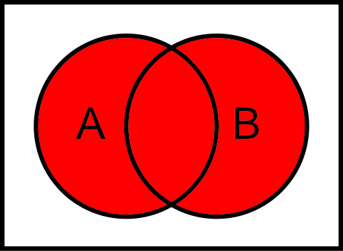
As we can see, both circles are completely shaded, showing that $ A \lor B $ contains all items in either $ A $ or $ B $, or both $ A $ and $ B $ at the same time.
This operation also easily extends to three variables. This truth table gives the value of $ A \lor B \lor C $ for all possible values of $ A $, $ B $, and $ C $.
| $ A $ | $ B $ | $ C $ | $ A \lor B \lor C $ |
|---|---|---|---|
| F | F | F | F |
| F | F | T | T |
| F | T | F | T |
| F | T | T | T |
| T | F | F | T |
| T | F | T | T |
| T | T | F | T |
| T | T | T | T |
The Venn diagram for this instance is very similar to the one above:
Once again, we see that all parts of the Venn diagram are shaded, except for the part outside of all the circles.
The last Boolean operator we’ll cover is exclusive or, or exclusive disjunction. We’ll sometimes see this referred to as xor as well. When written, we use the $ \oplus $ symbol. However, not all programming languages have implemented this operator, so there is no consistently used symbol in programming.
This operator works in the same way that “or” works in our spoken language. Recall the “Soup or Salad” example from earlier. The exclusive or operation is True if only one of the inputs is True. If both inputs are True, the output is False.
Here is a truth table giving the value of $ A \oplus B $ for all possible values of $ A $ and $ B $.
| $ A $ | $ B $ | $ A \oplus B $ |
|---|---|---|
| F | F | F |
| F | T | T |
| T | F | T |
| T | T | F |
As we can see, the result is True when either
$ A $ or
$ B $ are True, but it is False if both of them are True, or if both of them are False.
As a Venn diagram, it would look like this:
As we can see, the parts of the diagram in $ A $ and $ B $ are shaded, but the center part, which is in both $ A $ and $ B $, is not shaded.
This operation is most interesting when extended to three variables. This truth table gives the value of $ A \oplus B \oplus C $ for all possible values of $ A $, $ B $, and $ C $.
| $ A $ | $ B $ | $ C $ | $ A \oplus B \oplus C $ |
|---|---|---|---|
| F | F | F | F |
| F | F | T | T |
| F | T | F | T |
| F | T | T | F |
| T | F | F | T |
| T | F | T | F |
| T | T | F | F |
| T | T | T | T |
The Venn diagram for this instance is as follows:
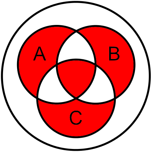
In this instance, we see the parts of the diagram representing items that are just in $ A $, $ B $, and $ C $ alone are shaded, as we’d expect. However, we also see the center of the diagram, representing items in $ A \land B \land C $ is also shaded. Interesting, isn’t it? Let’s see if we can break it down.
Just like we hopefully remember from mathematics, when we have multiple operations chained together, we must respect the order of operations. So, we can insert parentheses into the original statement to show how it would actually be calculated:
$ ((A \oplus B) \oplus C) $Now, let’s assume that all three of our variables are True, represented by
$ T $. So, we can reduce the first part as follows:
$$((A \oplus B) \oplus C) $$ $$((T \oplus T) \oplus T) $$ $$(F \oplus T) $$
As we can see, since
$ A $ and
$ B $ are both True, we find that
$ A \oplus B $ is False, as expected. Now, we can continue to reduce the expression:
$$ (F \oplus T) $$ $$ T $$
In this case, since only one of the two operands is True, the result of exclusive or would also be True. Therefore,
$ A \oplus B \oplus C $ is True when all three variables are True. In short, a string of exclusive ors is True if an odd number of the variables are True, and it is False if an even number of variables are True.
Not all languages support an logical exclusive or. Alternate forms are $ ( A \lor B) \land \lnot (A \land B) $ or $ (\lnot A \land B) \lor (A \land \lnot B) $.
At some restaurants, you are given a choice of not just two, but three items to go with your meal. Of course, the intent is for you to choose just one of the three items listed.
However, now that you understand how exclusive or works, you might see how you could get all three items instead of just one! Logic is pretty powerful, isn’t it?
Finally, it is worth discussing other operators that can result in a Boolean value. The most important of these operators are the comparators, which compare two values and return a result that is either True or False. We’ve definitely seen these operators before in mathematics, but may not have actually realized that they result in a Boolean value.
Below is a table giving the common comparators used in programming, along with an example of how they might be used:
| Name | Operator | Symbol | True Example |
False Example |
|---|---|---|---|---|
| Equal | $ = $ | == |
1 == 1 |
1 == 2 |
| Not Equal | $ \neq $ | != |
1 != 2 |
1 != 1 |
| Greater Than | $ > $ | > |
2 > 1 |
1 > 2 |
| Greater Than or Equal To | $ \geq $ | >= |
1 >= 1 |
1 >= 2 |
| Less Than | $ < $ | < |
1 < 2 |
2 < 1 |
| Less Than or Equal To | $ \leq $ | <= |
1 <= 1 |
2 <= 1 |
That covers all of the basic operators and symbols in Boolean logic. On the next page, we’ll learn how to combine them together and create logical statements using the rules of Boolean algebra.
The Venn diagrams are adapted from ones found on Wikimedia Commons ↩︎
Of course, one of the major goals of George Boole’s work was not only to create a system of logic that looked like math, but also to be able to apply some of the same techniques from math within that system. Boolean Algebra is a form of algebra that can be done on boolean expressions, and it contains many of the same laws and operations that we’ve already learned from algebra.
A Boolean expression is any expression that results in a Boolean value. They consist of the values True and False, sometimes denoted as
$ T $ and
$ F $, literal values, and variables which are usually lower-case letters, combined using the operations discussed on the previous page. Here are a few examples:
$$ T \land x $$ $$ (\neg x \land y) \oplus z $$ $$ (5 < x) \land (y > 8) $$
Boolean algebra contains many of the same laws found in algebra. Here is a table listing some of these laws with an example for each. If the law does not list a specific operation, then in general it will work for all operations.
| Name | Example |
|---|---|
| Associative | $ x \land (y \land z) \iff (x \land y) \land z $ |
| Commutative | $ x \land y \iff y \land x $ |
| Idempotence | $ x \land x \iff x $ |
| Distributive $ \land $ over $ \lor $ | $ x \land (y \lor z) \iff (x \land y) \lor (x \land z) $ |
| Distributive $ \lor $ over $ \land $ | $ x \lor (y \land z) \iff (x \lor y) \land (x \lor z) $ |
| Identity $ \land $ | $ x \land T \iff x $ |
| Identity $ \lor $ | $ x \lor F \iff x $ |
| Eliminate $ \land $ | $ x \land F \iff F $ |
| Eliminate $ \lor $ | $ x \lor T \iff T $ |
| Complement $ \land $ | $ x \land \neg x \iff F $ |
| Complement $ \lor $ | $ x \lor \neg x \iff T $ |
| Double Negative | $ \neg(\neg x) \iff x $ |
| Or Absorption | $ x \lor (x \land y) \iff x $ |
| And Absorption | $ x \land (x \lor y) \iff x $ |
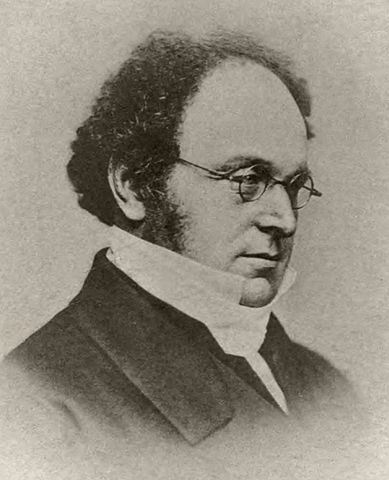
There is one rule, not listed above, where Boolean Algebra differs greatly from other forms of algebra. That is how it deals with the negation, or inverse, of an entire statement. For this, we refer to the work of Augustus De Morgan, pictured above. De Morgan was expanding upon the work of George Boole, and published some additional laws for Boolean Algebra, which we collectively refer to as De Morgan’s Laws.
In Algebra, when we negate an entire statement, we must change the signs of each number in the statement. Consider the example below:
$$ -(x + y) \iff -x + -y $$However, in Boolean Algebra, the same rules does not quite work:
$$ \neg(x \land y) \neq (\neg x) \land (\neg y) $$For example, if we assign the value True to
$ x $ and False to
$ y $, we would be able to reduce the expression in this way:
$$ \neg(x \land y) \neq (\neg x) \land (\neg y) $$ $$ \neg(T \land F) \neq (\neg T) \land (\neg F) $$ $$ \neg(F) \neq F \land T $$ $$ T \neq F $$
As we can see, the two statements are not equal. Instead, De Morgan’s Laws tell us that we must also invert the operation, changing $ \land $ to $ \lor $ and vice-versa. Let’s look at a corrected version of the above example:
$$ \neg(x \land y) \iff (\neg x) \lor (\neg y) $$ $$ \neg(T \land F) \iff (\neg T) \lor (\neg F) $$ $$ \neg(F) \iff (F) \lor (T) $$ $$ T \iff T $$
So, we must add the following two laws to our table above:
| Name | Example |
|---|---|
| De Morgan’s Law $ \land $ | $ \neg(x \land y) \iff (\neg x) \lor (\neg y) $ |
| De Morgan’s Law $ \lor $ | $ \neg(x \lor y) \iff (\neg x) \land (\neg y) $ |
That gives us a full suite of laws we can use when working in Boolean algebra.
We use DeMorgan’s all the time. When we say x is between 1 and 10, we can state that as either $ x \geq 1 \land x \leq 10 $ or $ \neg(x < 1 \lor x > 10) $. DeMorgan’s law provides the mathematical proof of this.
File:De Morgan Augustus.jpg. (2018, January 1). Wikimedia Commons, the free media repository. Retrieved 19:51, January 10, 2019 from https://commons.wikimedia.org/w/index.php?title=File:De_Morgan_Augustus.jpg&oldid=275794962. ↩︎
Now that we’ve learned about many of the laws of Boolean algebra, let’s go through a worked example, just to see how we can find a Boolean expression from a truth table. Programmers perform this process many times while writing code, since most programs include several boolean expressions. Those expressions control how the program performs in certain situations, such as when to repeat a block of code or when to choose between multiple blocks of code.
For this problem, let’s say we are working on a program to control smart lights. That program should turn the lights on if the light switch in the room is in the “ON” position. Similarly, it should turn on the lights if it detects there are people in the room using a motion sensor, regardless of whether the light switch is “ON” or “OFF”. However, it should respect a master switch, such that if the master switch is off, the lights can not be turned on at all.
How can we write a program that uses a Boolean expression to determine when to turn the lights on?
The first step is to create a truth table that describes the possible inputs and the desired outputs. For this example, we’ll assign input A to the light switch, input B to the motion sensor, and input C to the master switch. Using that, we can construct our truth table:
| A | B | C | Output |
|---|---|---|---|
| F | F | F | F |
| F | F | T | F |
| F | T | F | F |
| F | T | T | T |
| T | F | F | F |
| T | F | T | T |
| T | T | F | F |
| T | T | T | T |
In this table, we see that there are exactly three situations that cause the lights to be turned on, which is where the Output column contains True. They are highlighted in bold in this example. First, on the fourth line of the table, if the motion sensor input B is True, and the master switch input C is also True, then the output should be True. Similarly, the sixth line shows that if the light switch A is True and the master switch C is True, then the output is True. Finally, the last line shows that if all inputs are True, the output is True and the lights should be on.
Does that cover all of the situations where the lights should be on? Most of the remaining lines are situations where the master switch C is False, so the lights should not be turned on in any of those situations. The only exception is the second line, where the master switch C is True, but none of the other inputs are True. In that case, the lights should remain off.
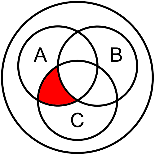
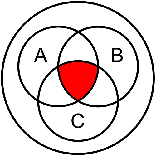
The next step is to make a Venn diagram. This step is not necessary, as we’ll see later, but it is a very helpful step to take when learning Boolean algebra for the first time. Each segment of the 3 variable Venn diagram corresponds to a particular line in the truth table, so we simply want to shade in each segment that corresponds to a line in the truth table where the output is True.
Let’s look at the first line where the output is True, which is the fourth line. In that line, we see that we need the part of the diagram that is contained in B and C, but not A. This is due to the fact that the inputs B and C are True, but input A is False on that line of the truth table. So, we’d shade in this segment of our Venn diagram:

The next line in the truth table where the output is True is the sixth line. In this line, we need the part that contains A and C but not B:
Finally, the last line in the truth table tells us that we must shade in the part of the diagram contained in all three circles, containing A and B and C together:
Now, we can put those sections together to find our overall Venn diagram for this statement:
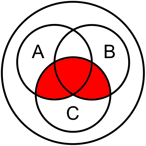
So, we can see that there are three segments shaded in our Venn diagram, corresponding to three lines in the truth table where the output is True. This gives us a helpful visual way to look at our Boolean logic expression.
Now that we’ve created a Venn diagram for this example, we can use it to create our Boolean expression. For this step, we’ll need to break the shaded part of the Venn diagram down into parts we can describe, and put those pieces together in a way that they represent the diagram as a whole. Let’s see how that works.
First, looking at our diagram, one thing we might notice is that it can be broken up into two overlapping segments. The first segment is this one:
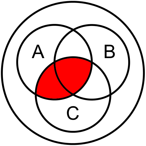
This diagram shows the part of the diagram that is included in both A and C. This is exactly the same as the 2 variable Venn diagram we saw on the previous page, especially if we ignore the circle for B. So, this diagram represents the Boolean expression $ A \land C $. That’s one piece of the puzzle.
The other segment we might see is this one:
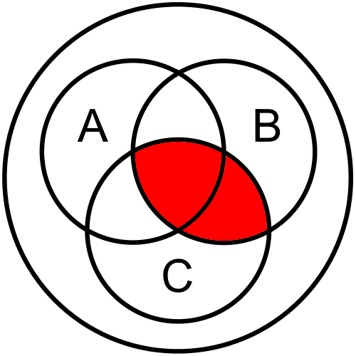
Similarly, this diagram represents the Boolean expression $ B \land C $, since it is the part of the diagram that is included in both B and C.
If we overlap those two segments, we would see the following result (with overlapping segments shaded a bit darker):
This is effectively the same diagram as we found above, isn’t it? That’s what we are aiming for!
So, we know that we need an expression that represents $ A \land C $ and $ B \land C $ overlapped. If we recall back to the basic Boolean operations, we should hopefully remember that the or operation does just that. So, we can use $ \lor $ to connect our two pieces, making the final Boolean expression:
$ (A \land C) \lor (B \land C) $Now that we have our final expression, let’s go back to the problem statement and see if it matches. Recall that it says we would like the lights turned on if the light switch is on and the master switch is on, or if the motion sensor senses people and the master switch is on. If we replace the variables in the Boolean expression, we see the following:
$ (\text{Light Switch} \land \text{Master Switch}) \lor (\text{Motion Sensor} \land \text{Master Switch}) $That is exactly what we want! So, we found the correct Boolean expression for our problem statement.
Of course, once you’ve seen the end result and compared it to the problem statement, it may be easy to see how you could quickly go directly from the problem statement to a Boolean expression without creating a truth table or a Venn diagram. In fact, if the problem statement is clear enough, it may already be structured exactly like a Boolean expression itself.
In practice, many programmers become familiar enough with Boolean expressions that they can easily go directly from a problem statement to a matching Boolean expression without much effort. It may seem difficult at first, but you’ll quickly become familiar with that process as you continue to write programs. For now, don’t be afraid to take the time and work each example through until you become more comfortable with it.
It usually takes at least a year or more of coding practice before this process feels simple. So, don’t sweat it!
We can also derive our Boolean expression directly from the data in the truth table, along with some of the Boolean Algebra laws we covered earlier in this chapter. Let’s go through an example of how that process works, just to see that we can get the same result.
In our truth table, we see that we should have three situations that provide output. The first is when B and C are True, while A is False. So, we could write that as the Boolean expression
$ \neg A \land B \land C $.
Similarly, we can do the same for the other two lines of output, which produce the expressions $ A \land \neg B \land C $ and $ A \land B \land C $, respectively.
Finally, we’d like our output to be True if at least one of those situations is True. So, we can use the or
$ \lor $ operation to connect them together into a single statement:
In fact, if we want, we can simply stop there. That statement is exactly equivalent to the one we found using the Venn diagrams above.
However, it is very long and difficult to understand directly, and it doesn’t clearly reflect our problem statement. So, let’s see if we can reduce this expression using the laws of Boolean Algebra to an equivalent one that is easier to read.
First, we must use the law of Idempotence to duplicate one of our terms. From that law, we know that the following is true:
$ (A \land B \land C) \iff (A \land B \land C) \lor (A \land B \land C) $So, we can replace the final term with this equivalent statement. We can do this here since it won’t affect the final outcome. It is the rough equivalent to adding $ 0 $ to an existing mathematical expression. So, our new expression is
$ (\neg A \land B \land C) \lor (A \land \neg B \land C) \lor (A \land B \land C) \lor (A \land B \land C) $Next, we can use the law of Commutativity to rearrange the terms a bit. This is the same as rewriting $ 1 + 2 $ as $ 2 + 1 $, so it is a simple law to apply:
$ (\neg A \land B \land C) \lor (A \land B \land C) \lor (\neg B \land A \land C) \lor (B \land A \land C) $We can also use the law of Associativity to add a few extra parentheses, just for clarity:
$ \bigg(\big(\neg A \land (B \land C)\big) \lor \big(A \land (B \land C)\big)\bigg) \lor \bigg(\big(\neg B \land (A \land C)\big) \lor \big(B \land (A \land C)\big)\bigg) $Next, we can apply the inverse of the Distributive law on the first block of statements to “factor out” the statement $ (B \land C) $, leaving this result:
$ \big((B \land C) \land (\neg A \lor A) \big) \lor \bigg(\big(\neg B \land (A \land C)\big) \lor \big(B \land (A \land C)\big)\bigg) $We can also do the same on the second block with $ (A \land C) $:
$ \big((B \land C) \land (\neg A \lor A) \big) \lor \big((A \land C) \land (\neg B \lor B)\big) $Next, we can use the Complement law to reduce both
$ (\neg A \lor A) $ and
$ (\neg B \lor B) $ to True:
Then, using the law of Identity, we know that $ x \land T \iff x $, so we can remove both instances of $ T $ in the expression:
$ (B \land C) \lor (A \land C) $Once again, we can apply the law of Commutativity to rearrange the terms to reach this final result:
$ (A \land C) \lor (B \land C) $There it is! We were able to use the laws of Boolean Algebra to prove that our Boolean expression found using the Venn diagrams is equivalent to the expression from the truth table. This process is very similar to the ones learned in an algebra class, but some of the laws are handled in a slightly different way.
Here’s a quick challenge: can you use the laws of Boolean Algebra to reduce that statement even more? See if you can find the answer before reading below.
It turns out that you can! We can apply the inverse of the Distributive law one more time to get the following result:
$ C \land (A \lor B) $
This also works, and might even fit better with the original problem statement. If we restate it as “the light should be on if the master switch is on and either the light switch is on or the motion sensor detects people,” the problem statement clearly reflects this answer as well. Both are equally correct in this case.
Not everyone finds the use of Venn diagrams easy or natural. Consider the following problem:
Determine if the value of the variable x is greater than 10, less than or equal to 30, and either divisible by both 2 and 3 or by 7.A Venn diagram of this statement would look something similar to this example:
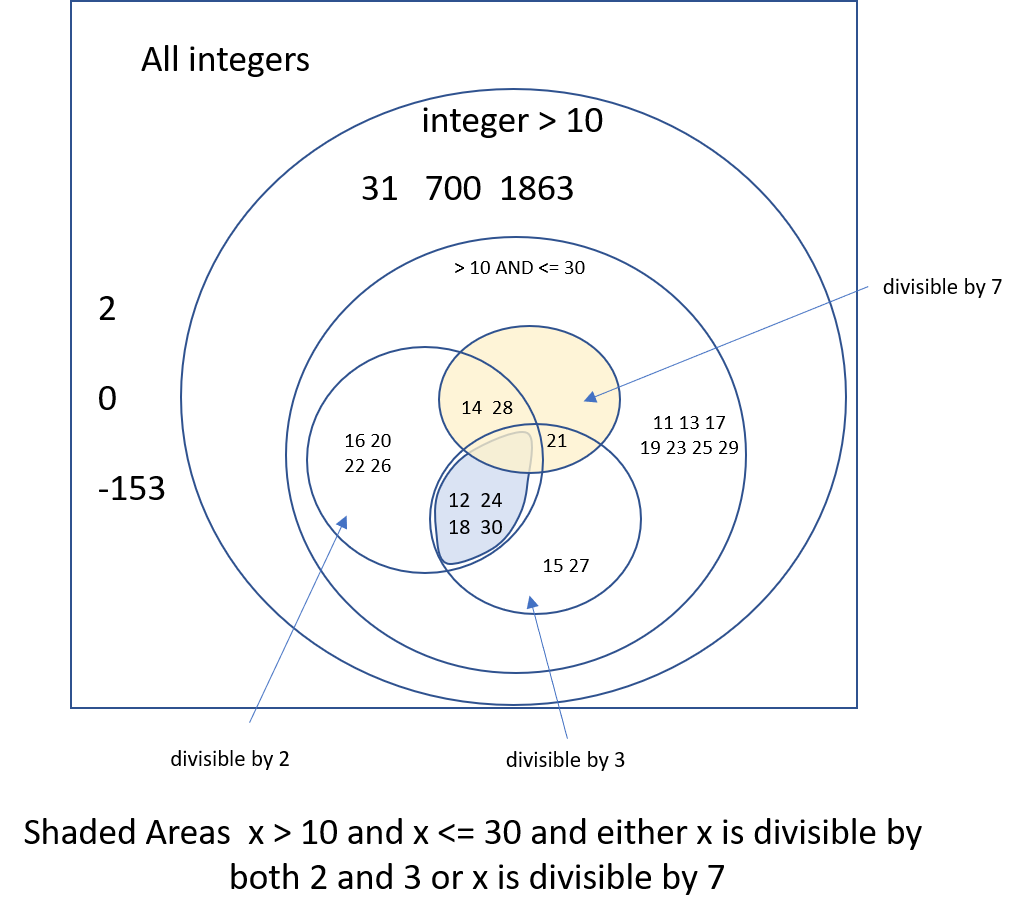
Unfortunately, it does not result in a graphic that is easily translatable to a Boolean logic statement. So, we’ll probably have to take another approach.
Instead, we can use the original problem statement as the structure to build a pseudocode representation that can eventually be translated to any programming language. We’ll begin by breaking down the original problem statement into smaller parts, as shown below:
Determine if the value of the variable x is:
  greater than 10
  less than or equal to 30
  and either
    divisible by both 2 and 3
    or by 7.
We’ve also added in a bit of indentation, just to make it easier to see the various parts of the statement.
Clearly the ands and ors in the original statement can be replaced with their Boolean equivalents. We’ll use capitalized AND, OR and NOT operators in text. Also, we can deduce that statements in a comma separated list should also be combined with AND, so we can update our statement as follows:
Determine if the value of the variable x is:
  greater than 10
  AND less than or equal to 30
  AND either
    divisible by both 2 AND 3
    OR by 7.
Next, we should try to make each statement closely resemble a written expression in code by adding in the implied subject of each statement and making them explicit. In most cases, we’ll add the variable x to the statement, as shown here:
Determine if the value of the variable x is:
  x greater than 10
  AND x less than or equal to 30
  AND either
    x divisible by 2 AND x divisible by 3
    OR x divisible by 7.
Notice how the statement divisible by both 2 and 3 was split into two parts. Each Boolean logic comparator requires a variable on each side, so we cannot write x divisible by 2 AND 3 as a valid statement. Instead, we have to split it into two statements, x divisible by 2 AND x divisible by 3. We also have to expand the line OR by 7 to clarify that it is also checking if x is divisible by 7, so we updated it to be x divisible by 7.
Now we can plug in the associated Boolean comparators and mathematical operators. Recall that we can check if a number is divisible by another number using the modulo operator; if that value modulo the divisor is 0, then we know the number is evenly divisible by the divisor. We’re also going to use the double equals sign == to denote equality, which is used in most programming languages.
Determine if the value of the variable x is:
  x > 10
  AND x <= 30
  AND either
    x % 2 == 0 AND x % 3 == 0
    OR x % 7 == 0.
Once we have that, we can go through and add in any missing parentheses. Notice that we originally used some tabs separate the various parts of the original statement, and those should closely align with where we need to add parentheses.
So, one possible way to interpret this statement is as follows:
x > 10 AND x <= 30 AND ((x % 2 == 0 AND x % 3 == 0) OR x % 7 == 0)This line of pseudocode is certainly easier translate into a programming language than using the Venn Diagram!
There is a technique in computer engineering used to express complicated Boolean expressions in the fewest number of operations. It is called the K-Map or Karnaugh Map technique. It is typically taught in introductory classes.
Certain applications areas of computer Science, particularly sub-fields such as artificial intelligence and control systems, end up producing long strings of Boolean algebra. Using both Karnaugh Maps and Boolean algebra techniques are used to reduce those statements.
While Boolean logic is very important when writing computer code, it is also a major part of working with computer hardware as well. In fact, most electronic hardware today uses chips and circuits that are built directly upon the fundamental building blocks of Boolean logic.
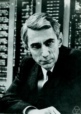
In 1937, a 21-year-old graduate student at MIT named Claude Shannon, pictured above, published his master’s thesis: “A Symbolic Analysis of Relay and Switching Circuits.” In that paper, he demonstrated how to build electric circuits which could perform all of the standard Boolean logic operations, using the presence or absence of an electric current or voltage to represent true and false in those circuits.
In addition, his work demonstrated that multiple circuits can be combined to perform simple mathematical operations on binary numbers, such as addition, subtraction, and even multiplication!
It is difficult to overstate the importance of Claude Shannon’s work in today’s modern world. Every electronic device we use is built upon the same fundamental concepts laid out by Shannon in the 1930s. In fact, one researcher described his work as “possibly the most important, and also the most famous, master’s thesis of the century.”2
Let’s look at an example of how Boolean logic can be used to perform mathematical operations. Here is a simple truth table showing addition using two binary bits as input. In this case,
$ 0 $ represents false and
$ 1 $ represents true:
| A | B | Carry (and) | Sum (xor) |
|---|---|---|---|
| 0 | 0 | 0 | 0 |
| 0 | 1 | 0 | 1 |
| 1 | 0 | 0 | 1 |
| 1 | 1 | 1 | 0 |
The addition itself is performed by the xor operation. For example, if both inputs are
$ 0 $, representing false, then the sum is
$ 0 + 0 = 0 $, which is false as well. However, if one input is
$ 1 $ and the other is
$ 0 $, then the sum is
$ 0 + 1 = 1 $ (which is the same as
$ 1 + 0 = 0 $), so the xor operation would output true. In both of those cases, the carry bit is
$ 0 $, since the sum does not require a bit to be carried forward to the left.
The interesting case is when both inputs are
$ 1 $. In this case, the result is
$ 1 + 1 = 2 $, where
$ 2 $ is represented by
$ 10 $ in binary. So, the sum result, represented by xor is false, but the carry bit, represented by the and operation, is true. So, the result would be
$ 10 $, represented by the carry bit followed by the sum.
So, we can represent the mathematical addition operation $ A + B $ using these two Boolean logic expressions:
The corresponding circuit for this operation is known as a half adder.
We can then expand this truth table to include a third input, which is the carry bit from a previous addition.
| A | B | Carry In | Carry Out | Sum |
|---|---|---|---|---|
| 0 | 0 | 0 | 0 | 0 |
| 0 | 0 | 1 | 0 | 1 |
| 0 | 1 | 0 | 0 | 1 |
| 0 | 1 | 1 | 1 | 0 |
| 1 | 0 | 0 | 0 | 1 |
| 1 | 0 | 1 | 1 | 0 |
| 1 | 1 | 0 | 1 | 0 |
| 1 | 1 | 1 | 1 | 1 |
From this truth table, we can find the following Boolean logic expressions for the sum and carry bits:
This circuit is known as a full adder.
So, given two binary bits as inputs $ A $ and $ B $, along with the carry bit from a previous addition $ C $, we can use these two Boolean expressions to find both the sum and carry bits as output.
To find the sum of larger numbers, we can simply chain together multiple instances of these full adder circuits together, moving through the binary number from left to right, just like we do for normal addition. In modern computers, the central processing unit, or CPU, contains circuits very similar to these to perform each mathematical instruction required to execute a program.
Wikibooks has a great page dedicated to this topic for additional information: Practical Electronics/Adders
File:ClaudeShannon MFO3807.jpg. (2018, December 28). Wikimedia Commons, the free media repository. Retrieved 19:09, January 14, 2019 from https://commons.wikimedia.org/w/index.php?title=File:ClaudeShannon_MFO3807.jpg&oldid=332553066. ↩︎
See https://en.wikipedia.org/wiki/A_Symbolic_Analysis_of_Relay_and_Switching_Circuits#cite_note-2 ↩︎
Boolean Logic in Java
The Java programming language supports Boolean values as a primitive data type named boolean. It also includes Boolean keywords true and false to represent each possible value. Notice that these keywords are not capitalized, unlike some other programming languages.
To declare a Boolean variable in Java, we can use the same basic syntax that we used for other variable types:
boolean b;We can then assign a value of true or false to that variable:
boolean b;
b = true;
We can also combine the two statements into a single statement:
boolean b = false;Java also supports most of the Boolean operators discussed earlier in the chapter. Let’s look at a few examples.
!In Java, the not operator is the exclamation point !, placed before a Boolean value. It will invert the value of the variable, changing true to false and false to true.
Here is a quick example:
boolean b = true;
boolean c = !b;
System.out.println(c); // false
This program will output false, which is the inverted value of b.
&&To perform the and operation, Java uses two ampersands && placed between Boolean values. Let’s look at an example:
boolean a = true;
boolean b = true;
boolean c = false;
System.out.println(a && b); // true
System.out.println(b && c); // false
This program will output true on the first line, since we know that both a and b are true. On the second line, it will output false, since c is false, even though b is true.
||Similarly, Java uses two vertical pipes || to represent the or operator. On most keyboards, we can find that key above the Enter key. Here’s an example of how it can be used in code:
boolean a = true;
boolean b = false;
boolean c = false;
System.out.println(a || b); // true
System.out.println(b || c); // false
Once again, this program will output true on the first line, since a is true, even though b is false. On the second line, it will output false, since both b and c are false.
According to the Java documentation, Java also supports using a single & for and, and a single | for or when dealing with Boolean values. Why shouldn’t we just use these operators instead?
It turns out that there is a fundamental difference in how the Java compiler handles these operators. The double-character operators && and || are called logical operators and short-circuit operators. In some scenarios, the system only needs to look at the first value in the statement to determine the result. For example, the statement x || (y || z) will always be true if x is true, without needing to consider the values in y or z. The same works for x && (y && z) when x is false, which will result in the entire statement being false. For larger Boolean expressions, the use of these short-circuit operators can make our programs run much faster and more efficiently.
The single-character operators & and | bit-wise comparison operators and are not short-circuited. So, the system will evaluate each part of the statement before determining the outcome. For boolean values, the bit-wise operators will evaluate to the same answer as the logical operators.
However you should not use them for this purpose. First, because they will slow your programs executions. Second, because it will obscure your intent to future readers of your program. At some distance point in the future, a programmer will see you used a bit-wise operator, assume there must be a reason you did not using the logical one, and lose valuable time trying to figure out why you did not use the logical operator.
You can read more about Bitwise Operations on Wikipedia. We will not use them in this course.
Java does not support a logical exclusive or, but we can build a similar statement using other operators.
boolean a = true;
boolean b = false;
boolean c = true;
System.out.println((a || b) && !(a && b)); // true
System.out.println((a || c) && !(a && c)); // false
In this example, the first line will be true, since a is true but b is false. However, the second line will output false, since both a and c are true .
We can also use the comparison operators ==, !=, <, <=, >, and >= to compare variables containing numbers, which will result in a Boolean value. Here’s an example showing those operators in action:
int x = 1;
int y = 2;
double z = 3.0;

System.out.println(x < y);  // true
System.out.println(x <= 1); // true
System.out.println(x > 2);  // false
System.out.println(x >= z); // false

System.out.println(x == 1); // true
System.out.println(x != y); // true
As we can see, each of the comparison operators works just as we’d expect, and outputs a Boolean value of either true or false, depending on the result of the comparison.
Like most high level languages, Java does not allow the chaining of comparison operators. 10 <= x <=20, which is a pretty standard math notation for x is between 10 and 20, will not work. First the compiler will evaluate 10 <=x as a boolean, then it will throw a fit about trying to compare a boolean and and int for the <= 20 part.
You will need to write this as 10 <= x && x <= 20.
Now that we’ve introduced some additional operators, we should also see where they fit in with the other operators in Java. Here is an updated list giving the appropriate operator precedence for Java, with new entries in bold:
++ & Decrement -- after variable*-, Not !, Increment ++ & Decrement -- before variable**, Division /, and Modulo %+, Subtraction -<, >, <=, >===, !=&&||=, +=, -=, *=, /=, %=Working with Boolean expressions in Java is the same as working with any other type of expression. So, we can use the same subgoals we learned in a previous chapter to help us evaluate and write new Boolean logic expressions. Here’s a quick review of those subgoals.
To analyze an expression involving variables and mathematical operators in code, here are some mental subgoals we can use:
First, we must determine whether the data type of the expression is compatible with the data type of the variable we want to store it in. In Java, we must be very careful to make sure we are only storing whole numbers in the integer data type, and floating point values in the double data type.
Next, we should look at the expression to determine if there are any prefixed operations that must occur first. In Java, for example, we could find a prefixed increment operator like ++x, so we’ll need to update the value of x before moving to the next step.
At this point, we can solve the arithmetic equation using the order of operations for our language. This simply involves the process of substituting values for variables and performing the requested operations. However, once again we must be careful to make sure that the operands provided to each operator are valid and produce the correct data type. The example we saw earlier for handling a large equation showed us a great way to work through this process.
Once we’ve solved the arithmetic equation, we should be left with a variable on the left side of the equals sign and a single value on the right side. So, once again, we should confirm that the value on the right can be stored in the data type of the variable on the left.
Finally, if the original expression included any postfix operations, such as a postfixed decrement like x-- in Java, we’ll need to update the value of x before moving on to the next line.
Here are the subgoals for writing a new expression:
The first step is to determine which part of the problem statement will be represented by a variable. Sometimes this is obvious, and other times it is not. This may be a new variable that we are creating, or it could be an update to an existing variable.
Once we’ve found a variable to work with, we must also determine the variable’s name and data type. Once again, this may be obviously found in the problem statement, but other times we must think a bit more about what type of data will be stored in the variable. Of course, we should also make sure the variable has a descriptive and memorable name if we are creating a new one.
Now that we’ve isolated our variable, we must build an arithmetic equation and operators required to produce the desired value. This may involve using additional variables in our equations as well.
Once we have our arithmetic equation, we can then build the overall expression. This usually consists of three parts: the variable on the left, an assignment operator in the middle, and the arithmetic equation on the right.
Finally, once we’ve constructed the overall expression, we should check and make sure that all operators and operands are compatible. This means making sure we are using the correct operators and conversions to produce the desired data type as output.
Let’s look at an example to see how we can use these steps to create an evaluate a Boolean expression to match a problem statement.
Consider the following problem statement:
Create a program to determine if a user has exactly 5 apples, or fewer oranges than bananas. If so, the program should output
true, otherwise it should outputfalse. For this program, assume the user has 4 apples, 6 oranges, and 8 bananas.
Let’s go through the subgoal steps above to write this program.
First, we can read the problem statement to see that we should have at least three variables - one for apples, oranges, and bananas. In addition, we may need a fourth variable to store the Boolean result that we’d like to output.
The second subgoal is pretty straightforward. We can easily create three integer variables, apples, oranges, and bananas for each type of fruit, and a Boolean variable result to store the result of our Boolean logic expression.
Next, we’ll need to build our arithmetic equation. For this program, we need to determine if the user has exactly 5 apples, or apples == 5. We also need to know if the user has fewer oranges than bananas, or oranges < bananas. Finally, we can put those together using the or operator as indicated in the problem statement, so the final equation would be (apples == 5) || (oranges < bananas).
Now we can build our program itself. Here’s one possible solution:
int apples = 4;
int oranges = 6;
int bananas = 8;

boolean result = (apples == 5) || (oranges < bananas);

System.out.println(result);||, we see that each side is a smaller expression that will result in a Boolean value, so the data type of each operand will be correct.Using subgoals makes it very easy to work through this process, one step at a time.
In this chapter, we learned all about Boolean logic, the corresponding rules for Boolean algebra, and how we can use those concepts to create our own Boolean logic expressions that we can use in our computer programs.
In the next chapters, we’ll see how we can use these expressions to control how our programs operate with programming constructs that allow our code to select between different branches or even repeat instructions as needed.