UML
A unified way to model your software’s structure!
A unified way to model your software’s structure!
Much of the content in this chapter was adapted from Nathan Bean’s CIS 400 course at K-State, with the author’s permission. That content is licensed under a Creative Commons BY-NC-SA license.
As software systems became more complex, it became harder to talk and reason about them. Unified Modeling Language (UML) attempted to correct for this by providing a visual, diagrammatic approach to communicate the structure and function of a program. If a picture is worth a thousand words, a UML diagram might be worth a thousand lines of code.
Some key terms to learn in this chapter are:
The key skill to learn in this chapter is how to draw UML class diagrams for programs we are developing.
Unified Modeling Language (UML) was introduced to create a standardized way of visualizing a software system design. It was developed by Grady Booch, Ivar Jacobson, and James Rumbah at Rational Software in the mid-nineties. It was adopted as a standard by the Object Management Group in 1997, and also by the International Organization for Standardization (ISO) as an approved ISO standard in 2005.
The UML standard actually provides many different kinds of diagrams for describing a software system - both structure and behavior:
The full UML specification is 754 pages long, so there is a lot of information packed into it. For the purposes of this class, we’re focusing on a single kind of diagram - the class diagram.
UML class diagrams are largely composed of boxes - basically a rectangular border containing text. UML class diagrams use boxes to represent units of code - i.e. classes, structs, and enumerations. These boxes are broken into compartments. For example, an Enum is broken into two compartments:
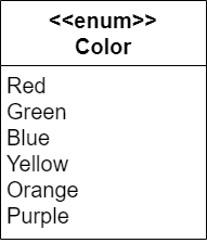
UML is intended to be language-agnostic. But we often find ourselves in situations where we want to convey language-specific ideas, and the UML specification leaves room for this with stereotypes. Stereotypes consist of text enclosed in double less than and greater than symbols. In the example above, we indicate the box represents an enumeration with the <<enum>> stereotype. Another commonly used stereotype is the <<interface>> stereotype that is used with interfaces in Java.
A second basic building block for UML diagrams is a typed element. Typed elements (as you might expect from the name) have a type. Fields and parameters are typed elements, as are method parameters and return values.
The pattern for defining a typed element is:
[visibility] element: type [constraint]The optional [visibility] indicates the visibility of the element, the element is the name of the typed element, and the type is its type, and the [constraint] is an optional constraint.
In UML visibility (based on access modifiers in Java, or the use of underscores in Python) is indicated with symbols, i.e.:
+ indicates public access.- indicates private access.# indicates protected access, which we will discuss in a later chapter.Consider, for example, a private size field. In a Java class, we would do the following:
private int size;Consider, for example, a private size field. In Python, we might have the following assignment in our constructor:
self.__size: int = 0;In a UML diagram, that field would be expressed as:
- size: intA typed element can include a constraint indicating some restriction for the element. The constraints are contained in a pair of curly braces after the typed element, and follow the pattern:
{element: boolean expression}For example:
- age: int {age: >= 0}indicates the private variable age must be greater than or equal to 0.
In a UML class diagram, individual classes are represented with a box divided into three compartments, each of which is for displaying specific information:

The first compartment identifies the class - it contains the name of the class. The second compartment holds the attributes of the class (the fields and properties). And the third compartment holds the operations of the class (the methods) of the class.
In the diagram above, we can see the Fruit class modeled on the right side.
UML is a very flexible tool, but it can become difficult to create UML diagrams that accurately reflect the differences between programming languages. So, different developers might implement the same UML class diagram in slightly different ways.
For example, in Java we would use a boolean data type to represent a Boolean value, whereas Python uses the bool type. Likewise, Java also includes a class called Boolean that is an object wrapper around a primitive boolean variable, allowing it to be used in various Java collections. Additionally, some other languages do not include a Boolean data type at all, and instead use a small integer with 0 representing true and other values representing false.
In prior CC courses, it was important for the software to exactly match the specification so that our autograders would work. In that case, we provided UML diagrams that were somewhat unique to each programming language. For this course, we will create UML diagrams that are a bit more generalized.
In the descriptions below, we’ll include discussions of ways to properly represent each UML element for each language, but it may allow for some flexibility. In general, as long a similarly experienced developer can follow the UML diagram and/or the source code and correlate the two, we will consider that good enough.
The attributes in UML represent the state of an object. For most object-oriented languages, this would correspond to the fields and properties of the class.
We indicate fields in our UML diagram with a typed element. So, to create a private Boolean variable named blended, we would include the following:
- blended: boolean- blended: boolFor Python, we may also choose to include the underscores in front of the name to show that it should be treated as a private attribute, as implied by the - at the start of the element:
- __blended: boolHowever, this can make the UML a bit more difficult to read, so we generally won’t do this in the UML diagrams in this course.
Java and Python handle accessor methods differently, and they can be denoted in UML in many different ways.
A general solution would be to include a stereotype after the element, indicating if a public getter or setter should be created for that element. So, to create a getter and a setter for our blended attribute, we could do the following:
- blended: boolean <<get,set>>- blended: bool <<get,set>>Of course, each language would handle this a bit differently. In Java, we would create public getBlended() and setBlended(boolean) methods in our class. In Python, we would use the @property and @blended.setter decorators to create a Python property. While all of those are technically methods, they are really meant to implement the functionality of an attribute, so we’ll treat them as part of the attribute in UML.
What if our accessors implement unique functionality, or we want one of them to be protected instead of public? In those cases, we may want to include the explicit accessor methods as operations as described below. However, in general, it is best practice to make our UML as concise as possible, so we generally don’t list accessor methods directly unless there is a good reason to do so.
The operations in UML represent the behavior of the object, i.e. the methods we can invoke upon it. These are declared using the pattern:
visibility name([parameter list])[:return type]The [visibility] portion uses the same symbols as typed elements, with the same correspondences. The name is the name of the method, and the [parameter list] is a comma-separated list of typed elements, corresponding to the parameters of the method. The [:return type] indicates the return type for the method. That portion can be omitted if the method doesn’t explicitly return a value (void in Java or None in Python).
Thus, in the example above, the protected method Blend has no parameters and returns a string.
Consider a method that adds together two integers and returns the result. The examples below show how the method’s signature corresponds to its UML element.
public int add(int a, int b){
    return a + b;
}
def add(a: int, b: int) -> int:
return a + b+ add(a: int, b: int): intIn UML, we indicate a class is static by underlining its name in the first compartment of the class diagram. We can similarly indicate operations and methods are static by underlining the entire line referring to them.
To indicate a class is abstract, we italicize its name. Abstract methods are also indicated by italicizing the entire line referring to them.
We’ll talk more about some of these concepts in a later chapter.
Class diagrams also express the associations between classes by drawing lines between the boxes representing them.
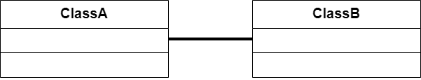
There are two basic types of associations we model with UML: has-a and is-a associations. We break these into two further categories, based on the strength of the association, which is either strong or weak. These associations are:
| Association Name | Association Type | Typical Usage |
|---|---|---|
| Realization | weak is-a | Interfaces |
| Generalization | strong is-a | Inheritance |
| Aggregation | weak has-a | Collections |
| Composition | strong has-a | Encapsulation |
Is-a associations indicate a relationship where one class is a instance of another class. Thus, these associations represent polymorphism, where a class can be treated as another class, i.e. it has both its own, and the associated classes’ types.
Realization refers to making an interface “real” by implementing the methods it defines. An interface is a special type of abstract class that only includes abstract methods. In effect, it is creating an defined list of operations, or an interface (or API), that subclasses must include so that they can all be used in the same way. For Java, this corresponds to a class that implements an interface. The Python language doesn’t have interfaces, but we’ll learn how to create something similar using abstract classes. We call this a is-a relationship, because the class can be treated as being the same data type of the interface class. It is also a weak relationship as the same interface can be implemented by otherwise unrelated classes. In UML, realization is indicated by a dashed arrow in the direction of implementation:

Generalization refers to extracting the shared parts from different classes to make a general base class of what they have in common. For Java and Python, this corresponds to inheritance. We call this a strong is-a relationship, because the class has all the same state and behavior as the base class. In UML, realization is indicated by a solid arrow in the direction of inheritance:

Also notice that we show that Fruit and its blend() method are abstract by italicizing them. The association tells us that the Banana class is a Fruit.
Has-a associations indicates that a class holds one or more references to instances of another class. In Java or Python, this corresponds to having a variable or collection with the type of the associated class. This is true for both kinds of has-a associations. The difference between the two is how strong the association is.
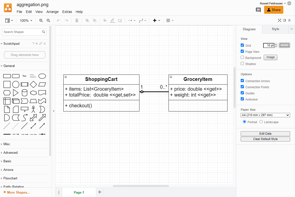
Aggregation refers to collecting references to other classes. As the aggregating class has references to the other classes, we call this a has-a relationship. It is considered weak because the aggregated classes are only collected by the aggregating class, and can exist on their own. It is indicated in UML by a solid line from the aggregating class to the one it aggregates, with an open diamond “fletching” on the opposite site of the arrow (the arrowhead is optional).

Composition refers to assembling a class from other classes, “composing” it. As the composed class has references to the other classes, we call this a has-a relationship. However, the composing class typically creates the instances of the classes composing it, and they are likewise destroyed when the composing class is destroyed. For this reason, we call it a strong relationship. It is indicated in UML by a solid line from the composing class to those it is composed of, with a solid diamond “fletching” on the opposite side of the arrow (the arrowhead is optional).

Aggregation and composition are commonly confused, especially given they both are defined by holding a variable or collection of another class type. Here’s a helpful analogy to explain the difference, based on the diagrams listed above:
Aggregation is like a shopping cart. When you go shopping, you place groceries into the shopping cart, and it holds them as you push it around the store. Thus, a ShoppingCart class might have a List<Grocery> named items, and you would add the items to it. When you reach the checkout, you would then take the items back out. The individual Grocery objects existed before they were aggregated by the ShoppingCart, and also after they were removed from it. The ShoppingCart class just keeps track of them.
In contrast, composition is like an organism. Say we create a class representing a Dog. It might be composed of classes like Tongue, Ear, Leg, and Tail. We would probably construct these parts in the Dog class’s constructor, and when we dispose of the Dog object, we wouldn’t expect these component classes to stick around. So, they are inherently a part of the encapsulating class.
Additionally, sometimes the attributes containing these external items may be omitted from the UML diagram of the composing or aggregating class. This is mainly because the existence of those attributes can be inferred by the relationships themselves. However, in this course, we will include the relevant attributes in the encapsulating class, as well as the association arrows, in our UML diagrams
With aggregation and composition, we may also place numbers on either end of the association, indicating the number of objects involved. We call these numbers the multiplicity of the association.
For example, the Frog class in the composition example has two instances of front and rear legs, so we indicate that each Frog instance (by a 1 on the Frog side of the association) has exactly two (by the 2 on the leg side of the association) legs. The tongue has a 1 to 1 multiplicity as each frog has one tongue.
Multiplicities can also be represented as a range (indicated by the start and end of the range separated by ..). We see this in the ShoppingCart example above, where the count of GroceryItems in the cart ranges from 0 to infinity (infinity is indicated by an asterisk *).
Generalization and realization are always one-to-one multiplicities, so multiplicities are typically omitted for these associations.
There are many tools available to help you develop your own UML diagrams. Here are a few that we recommend using for this course.
Most of the graphics used in the Computational Core program, including the UML diagrams in this and previous courses, are made using the free Diagrams.net tool.
When creating a new diagram, you can select the UML Diagram template to get started. The interface is really simple and easy to use, with lots of drag-and-drop components you can add to your diagram.
To create multiplicities, you can simply add text boxes to your arrows.
To export a diagram, click the File menu and choose the Export To option. You can create both PNG and SVG files!
One great feature of Diagrams.net is the ability to embed the diagram data directly into an image file exported from the application. In that way, we only have to have access to the image in order to open the diagram and update the image.
Try it yourself! Right-click on a UML diagram in this book to download it as an image, and then open the image using the upload option in Diagrams.net. You should be able to edit the diagram!
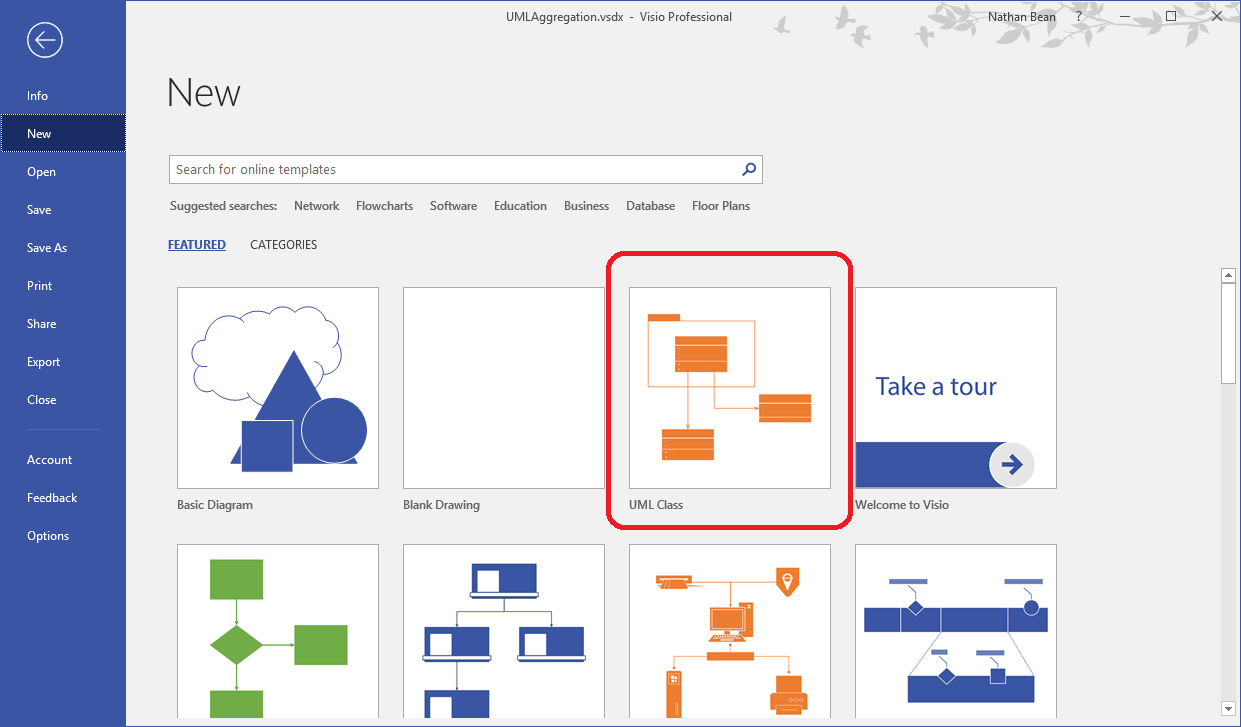
Another tool we can use to create UML diagrams is Microsoft Visio. For Kansas State University Computer Science students, this can be downloaded through your Azure Student Portal.
Visio is a vector graphics editor for creating flowcharts and diagrams. it comes preloaded with a UML class diagram template, which can be selected when creating a new file:
Class diagrams are built by dragging shapes from the shape toolbox onto the drawing surface. Notice that the shapes include classes, interfaces, enumerations, and all the associations we have discussed. Once in the drawing surface, these can be resized and edited.
Right-clicking on an association will open a context menu, allowing you to turn on multiplicities. These can be edited by double-clicking on them. Unneeded multiplicities can be deleted.
To export a Visio project in PDF or other form, choose the “Export” option from the file menu.
Let’s work through an example of creating a UML class diagram based on existing code. This is loosely based off a project from an earlier course, so some of the structure may be familiar.
This project is a number calculator that makes use of object-oriented concepts such as inheritance, interfaces, and polymorphism to represent different types of numbers using different classes. We’ll also follow the Model-View-Controller (MVC) architectural pattern.
We’ll start by looking at the Number interface, which is the basis of all of the number classes. We’re omitting the method code in these examples, since we are only concerned with the overall structure of the classes themselves.
public interface Number {
    Number add(Number n);
    Number subtract(Number n);
    Number multiply(Number n);
    Number divide(Number n);
}
class Number(metaclass=abc.ABCMeta):
@classmethod
def __subclasshook__(cls, subclass: type) -> bool:
@abc.abstractmethod
def add(self, n: Number) -> Number:
@abc.abstractmethod
def subtract(self, n: Number) -> Number:
@abc.abstractmethod
def multiply(self, n: Number) -> Number:
@abc.abstractmethod
def divide(self, n: Number) -> Number:In UML, we’d represent this interface using the following box. It includes the <<interface>> stereotype, as well as the listed methods shown in italics since they are all abstract. Finally, each method in an interface is assumed to be public, so we’ll include a plus symbol + in front of each method.

Next is the class for representing real numbers. This class will be a realization of the Number interface, as we can see in the code:
public class RealNumber implements Number {

    private double value;

    public RealNumber(double value){ }

    public Number add(Number n){ }

    public Number subtract(Number n){ }

    public Number multiply(Number n){ }

    public Number divide(Number n){ }

    @Override
    public String toString(){ }

    @Override
    public boolean equals(Object o){ }
}
class RealNumber(Number):
def __init__(self, value: float) -> None:
self.__value = value
def add(self, n: Number) -> Number:
def subtract(self, n: Number) -> Number:
def multiply(self, n: Number) -> Number:
def divide(self, n: Number) -> Number:
def __str__(self) -> str:
def __eq__(self, o: object) -> bool:it also includes implementations for a couple of other methods beyond the interface, including a constructor. So, in our UML diagram, we’ll add another box to represent that class, and use the realization association arrow to show the connection between the classes. Remember that the arrow itself points toward the interface or parent class.

From here, it’s pretty easy to see how we can use inheritance to create a RationalNumber class and an IntegerNumber class. The only way that they differ from the RealNumber class are the attributes. So, we’ll quickly add those to our UML diagram as well.

At this point, we can add a new class to represent complex numbers. A complex number consists of two parts - a real part and an imaginary part. So, it will both implement the Number interface, but it will also be composed of two RealNumber attributes. Notice that we’re using RealNumber as the attribute instead of the Number interface. This is because we don’t want a complex number to contain a complex number, so we’re being careful about our inheritance. In code, this class would look like this:
public class ComplexNumber implements Number {

    private RealNumber real;
    private RealNumber imaginary;

    public ComplexNumber(RealNumber real, RealNumber imaginary){ }

    public Number add(Number n){ }

    public Number subtract(Number n){ }

    public Number multiply(Number n){ }

    public Number divide(Number n){ }

    @Override
    public String toString(){ }

    @Override
    public boolean equals(Object o){ }
}
class ComplexNumber(Number):
def __init__(self, real: RealNumber, imaginary: RealNumber) -> None:
self.__real = real
self.__imaginary = imaginary
def add(self, n: Number) -> Number:
def subtract(self, n: Number) -> Number:
def multiply(self, n: Number) -> Number:
def divide(self, n: Number) -> Number:
def __str__(self) -> str:
def __eq__(self, o: object) -> bool:In our UML diagram, we’ll add a box for this class. We’ll also add both a realization association to the Number interface, but also a composition association to the RealNumber class, complete with the cardinality of the relationship.

Once we’ve created all of our number classes, we can quickly create our View and Controller classes as well. They will handle getting input from the user, performing operations, and displaying the results.
public class View {

    public View(){ }

    public void show(Number n){ }

    public String input(){ }

}

public class Controller {

    private List<Number> numbers;
    private View view;

    public Controller(){ }

    public void build(){ }

    public void sum(){ }

    public static void main(String[] args){ }
}
class View:
def __init__(self) -> None:
def show(self, n: Number) -> None:
def input(self) -> str:
class Controller:
def __init__(self) -> None:
self.__numbers: List[Number] = list()
self.__view: View = View()
def build(self) -> None:
def sum(self) -> None:
@classmethod
def main(self, args: List[str]) -> None:In the code, we see that the Controller class contains an attribute for a single View() instance, and also a list of Number instances. So, we’ll end up using a composition association between Controller and View, and an aggregation association between Controller and the Number interface.

This is a small example, but it demonstrates many of the important object-oriented concepts in a single UML diagram:
Number class is an interface and abstract classRealNumber implements the Number class through a realization associationRationalNumber and IntegerNumber show direct inheritance through a generalization associationImaginaryNumber contains two RealNumber instances, showing the composition association and a multiplicity of 2.Controller, View and Number classes make up the various parts of an MVC architecture.Controller stores a list of Number instances, demonstrating the aggregation association.Controller also contains a single View instance, which is another composittion association with multiplicity of 1.UML is a very broad topic to cover in a single module, let alone a single class. For more information on building and reading UML diagrams, refer to these sources:
There are also many textbooks devoted to teaching UML concepts, as well as lots of examples online to learn from. The O’Reilly subscription through the K-State Libraries offers several books to choose from that can be accessed for free through this link:
In this section, we learned about UML class diagrams, a language-agnostic approach to visualizing the structure of an object-oriented software system. We saw how individual classes are represented by boxes divided into three compartments; the first for the identity of the class, the second for its attributes, and the third for its operators. We learned that italics are used to indicate abstract classes and operators, and underlining static classes, attributes, and operators.
We also saw how associations between classes can be represented by arrows with specific characteristics, and examined four of these in detail: aggregation, composition, generalization, and realization. We also learned how multiplicities can show the number of instances involved in these associations.
Finally, we saw how classes, interfaces, and enumerations are modeled using UML. We saw how the stereotype can be used to indicate language-specific features like properties. We also looked at creating UML class diagrams using Diagrams.net and Microsoft Visio.
Check your understanding of the new content introduced in this chapter below - this quiz is not graded and you can retake it as many times as you want.
