Operators and Circuits
In this chapter, we review basic notions about gates and learn the relationship between circuits and assignment-based computer programs. This sets the stage for analyzing modern programs.
Logical operators
There are four basic logic gates, with corresponding logical operators:
| Meaning | Logical Operator | Logic Gate |
|---|---|---|
| p AND q | p ∧ q | 
|
| p OR q | p ∨ q | 
|
| NOT p | ¬p | 
|
| p IMPLIES q | p → q | 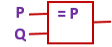
|
In the above drawings, the input wires are labelled with the names P and Q. The output that is computed is emitted from the rightmost wire which exits the gate. For these simple gates, it is possible to exhaustively test every permutation of potential inputs and summarize results in a table, called a truth table.
Let’s examine the AND gate. The AND gate emits a high voltage (1) exactly when high voltages are sensed at input wires P and Q; otherwise low voltage (0) is emitted. The gate’s physical behavior is summarized by in the following table:
AND: P Q |
-------------
     1 1 | 1
     1 0 | 0
     0 1 | 0
     0 0 | 0
Truth tables
For the remainder of this course, we will use T (read “true”) for 1 and F (read “false”) for 0. This is because we will examine applications that go far beyond circuit theory and base-two arithmetic. Here are the truth tables for the AND, OR, NOT and IMPLIES gates:
AND: P Q |
-------------
     T T | T
     T F | F
     F T | F
     F F | F


OR: P Q |
-------------
     T T | T
     T F | T
     F T | T
     F F | F


NOT: P |
-------------
     T | F
     F | T


IMPLIES: P Q |
-----------------
         T T | T
         T F | F
         F T | T
         F F | T
A few comments:
The OR gate is inclusive – as long as one of its inputs is true, then its output is true.
You might be confused by the IMPLIES gate. We’ll cover it in detail below.
In the next section, we will learn to write our truth tables in a slightly different format so they can be automatically checked by Sireum Logika.
Implies operator
The implies operator can be difficult to understand. It helps to think of it as a promise: we write P → Q, but we mean If P is true, then I promise that Q will also be true. If we BREAK our promise (i.e., if P is true but Q is false), then the output of an implies gate is false. In every other situation, the output of the implies gate is true.
As a reminder, here is the truth table for the implies operator, → :
P Q | P → Q
-----------------
T T |   T
T F |   F
F T |   T
F F |   T
It is likely clear why P → Q is true when both P and Q are true – in this situation, we have kept our promise.
It is also easy to understand why P → Q is false when P is true and Q is false. Here, we have broken our promise – P happened, but Q did not.
In the other two cases for P → Q we have that P is false (and Q is either true or false). Here, P → Q is true simply because we haven’t broken our promise. In these cases, the implication is said to be vacuously true because we have no evidence to prove that it is false.
Circuits
We can also compose the gates to define new operations.
For example, this circuit:
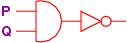
Written ¬(P ∧ Q), defines this computation of outputs:
P Q | ¬(P ∧ Q)
-----------------
T T | F
T F | T
F T | T
F F | T
We can work out the outputs in stages, like this:
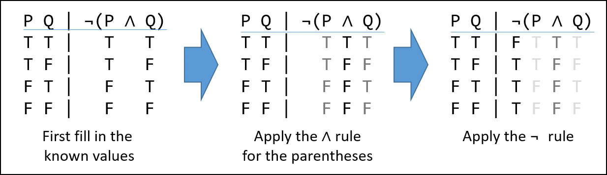
We begin by writing the value of each set of inputs on the left, under their corresponding symbol on the right. Next we apply the operator (gate) with the highest precedence (covered in Operator Precedence in the next section). In our case the () make the AND ( ∧ ) symbol the highest.
A truth assignment is a unique permutation of the possible inputs for a system. For the ∧-gate, it is a 2-variable sequence. Considering the first row we see we have T ∧ T. Looking that up in the ∧-gate truth table we see the result is also “T”, and we record that under the ∧ symbol. We do the same thing all the other truth assignments.
After the initial transcribing of the truth values under their respective variables, we look up the truth-values in the gate tables, not the variables. Also observe that while ∧ is symmetric – i.e. T ∧ F and F ∧ T are both false – the IMPLIES gate is not.
Now we look up the value under the ∧ symbol in the ¬ gate table. In the first row we see that the truth assignment for the first row, “T”, is “F” and record it under the ¬ symbol. Do this for every row and we are done.