UML
The Standard Model of Object-Orientation
The Standard Model of Object-Orientation
As software systems became more complex, it became harder to talk and reason about them. Unified Modeling Language (UML) attempted to correct for this by providing a visual, diagrammatic approach to communicate the structure and function of a program. If a picture is worth a thousand words, a UML diagram might be worth a thousand lines of code…
Some key terms to learn in this chapter are:
The key skill to learn in this chapter is how to draw UML class diagrams.
Unified Modeling Language (UML) was introduced to create a standardized way of visualizing a software system design. It was developed by Grady Booch, Ivar Jacobson, and James Rumbah at Rational Software in the mid-nineties. It was adopted as a standard by the Object Management Group in 1997, and also by the International Organization for Standardization (ISO) as an approved ISO standard in 2005.
The UML standard actually provides many different kinds of diagrams for describing a software system - both structure and behavior:
The full UML specification is 754 pages long, so there is a lot of information packed into it. For the purposes of this class, we’re focusing on a single kind of diagram - the class diagram.
UML class diagrams are largely composed of boxes - basically a rectangular border containing text. UML class diagrams use boxes to represent units of code - i.e. classes, structs, and enumerations. These boxes are broken into compartments. For example, an Enum is broken into two compartments:
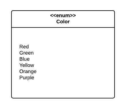
UML is intended to be language-agnostic. But we often find ourselves in situations where we want to convey language-specific ideas, and the UML specification leaves room for this with stereotypes. Stereotypes consist of text enclosed in double less than and greater than symbols. In the example above, we indicate the box represents an enumeration with the $ \texttt{<<enum>>}$ stereotype.
A second basic building block for UML diagrams is a typed element. Typed elements (as you might expect from the name) have a type. Fields and parameters are typed elements, as are method parameters and return values.
The pattern for defining a typed element is:
$$ \texttt{[visibility] element : type [constraint]} $$The optional $\texttt{[visibility]}$ indicates the visibility of the element, the $\texttt{element}$ is the name of the typed element, and the $\texttt{type}$ is its type, and the $\texttt{[constraint]}$ is an optional constraint.
In UML visibility (what we would call access level in C#) is indicated with symbols, i.e.:
publicprivateprotectedI.e. the field:
protected int Size;Would be expressed:
$$ \texttt{# Size : int} $$A typed element can include a constraint indicating some restriction for the element. The constraints are contained in a pair of curly braces after the typed element, and follow the pattern:
$$ \texttt{ {element: boolean expression} } $$For example:
$$ \texttt{- age: int {age: >= 0}} $$Indicates the private variable age must be greater than or equal to 0.
In a UML class diagram, individual classes are represented with a box divided into three compartments, each of which is for displaying specific information:
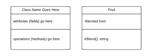
The first compartment identifies the class - it contains the name of the class. The second compartment holds the attributes of the class (in C#, these are the fields and properties). And the third compartment holds the operations of the class (in C#, these are the methods).
In the diagram above, we can see the Fruit class modeled on the right side.
The attributes in UML represent the state of an object. For C#, this would correspond to the fields and properties of the class.
We indicate fields with a typed element, i.e. in the example above, the blended field is represented with:
Indicating it should be declared private with the type bool.
For properties, we add a stereotype containing either get, set, or both. I.e. if we were to expose the private field bool with a public accessor, we would add a line to our class diagram with:
In C#, properties are technically methods. But we use the same syntax to utilize them as we do fields, and they serve the same role - to expose aspects of the class state. So for the purposes of this class we’ll classify them as attributes.
The operators in UML represent the behavior of the object, i.e. the methods we can invoke upon it. These are declared using the pattern:
$$ \texttt{visibility name([parameter list])[:return type]} $$The $\texttt{[visibility]}$ uses the same symbols as typed elements, with the same correspondences. The $\texttt{name}$ is the name of the method, and the $\texttt{[parameter list]}$ is a comma-separated list of typed elements, corresponding to the parameters. The $\texttt{[:return type]}$ indicates the return type for the method (it can be omitted for void).
Thus, in the example above, the protected method Blend has no parameters and returns a string. Similarly, the method:
public int Add(int a, int b)
{
    return a + b;
}
Would be expressed:
$$ \texttt{+Add(a:int, b:int):int} $$In UML, we indicate a class is static by underlining its name in the first compartment of the class diagram. We can similarly indicate static operators and methods by underlining the entire line referring to them.
To indicate a class is abstract, we italicize its name. Abstract methods are also indicated by italicizing the entire line referring to them.
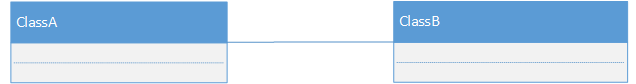
Class diagrams also express the associations between classes by drawing lines between the boxes representing them.
There are two basic types of associations we model with UML: has-a and is-a associations. We break these into two further categories, based on the strength of the association, which is either strong or weak. These associations are:
| Association Name | Association Type |
|---|---|
| Realization | weak is-a |
| Generalization | strong is-a |
| Aggregation | weak has-a |
| Composition | strong has-a |
Is-a associations indicate a relationship where one class is a instance of another class. Thus, these associations represent polymorphism, where a class can be treated as another class, i.e. it has both its own, and the associated classes’ types.
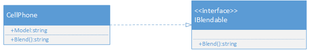
Realization refers to making an interface “real” by implementing the methods it defines. For C#, this corresponds to a class that is implementing an Interface. We call this a is-a relationship, because the class is treated as being the type of the Interface. It is also a weak relationship as the same interface can be implemented by otherwise unrelated classes. In UML, realization is indicated by a dashed arrow in the direction of implementation:
Generalization refers to extracting the shared parts from different classes to make a general base class of what they have in common. For C# this corresponds to inheritance. We call this a strong is-a relationship, because the class has all the same state and behavior as the base class. In UML, generalization is indicated by a solid arrow in the direction of inheritance:
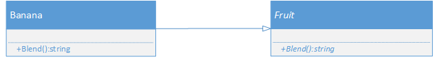
Also notice that we show that Fruit and its Blend() method are abstract by italicizing them.
Has-a associations indicates that a class holds one or more references to instances of another class. In C#, this corresponds to having a variable or collection with the type of the associated class. This is true for both kinds of has-a associations. The difference between the two is how strong the association is.
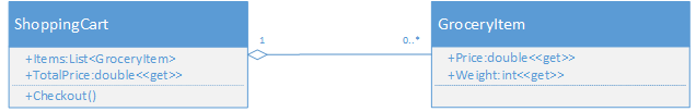
Aggregation refers to collecting references to other classes. As the aggregating class has references to the other classes, we call this a has-a relationship. It is considered weak because the aggregated classes are only collected by the aggregating class, and can exist on their own. It is indicated in UML by a solid line from the aggregating class to the one it aggregates, with an open diamond “fletching” on the opposite side of the arrow (the arrowhead is optional).
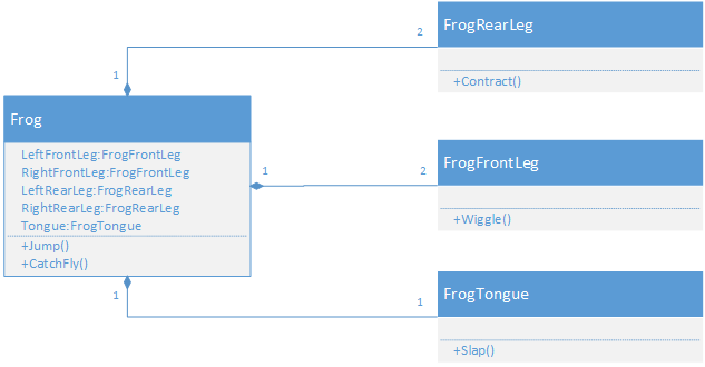
Composition refers to assembling a class from other classes, “composing” it. As the composed class has references to the other classes, we call this a has-a relationship. However, the composing class typically creates the instances of the classes composing it, and they are likewise destroyed when the composing class is destroyed. For this reason, we call it a strong relationship. It is indicated in UML by a solid line from the composing class to those it is composed of, with a solid diamond “fletching” on the opposite side of the arrow (the arrowhead is optional).
Aggregation and composition are commonly confused, especially given they both are defined by holding a variable or collection of another class type. An analogy I like to use to help students reason about the difference is this:
Aggregation is like a shopping cart. When you go shopping, you place groceries into the shopping cart, and it holds them as you push it around the store. Thus, a ShoppingCart class might have a List<Grocery> named Contents, and you would add the items to it. When you reach the checkout, you would then take the items back out. The individual Grocery objects existed before they were aggregated by the ShoppingCart, and also after they were removed from it.
In contrast, Composition is like an organism. Say we create a class representing a Dog. It might be composed of classes like Tongue, Ear, Leg, and Tail. We would probably construct these in the Dog class’s constructor, and when we dispose of the Dog object, we wouldn’t expect these component classes to stick around.
With aggregation and composition, we may also place numbers on either end of the association, indicating the number of objects involved. We call these numbers the multiplicity of the association.
For example, the Frog class in the composition example has two instances of front and rear legs, so we indicate that each Frog instance (by a 1 on the Frog side of the association) has exactly two (by the 2 on the leg side of the association) legs. The tongue has a 1 to 1 multiplicity as each frog has one tongue.
Multiplicities can also be represented as a range (indicated by the start and end of the range separated by ..). We see this in the ShoppingCart example above, where the count of GroceryItems in the cart ranges from 0 to infinity (infinity is indicated by an asterisk *).
Generalization and realization are always one-to-one multiplicities, so multiplicities are typically omitted for these associations.
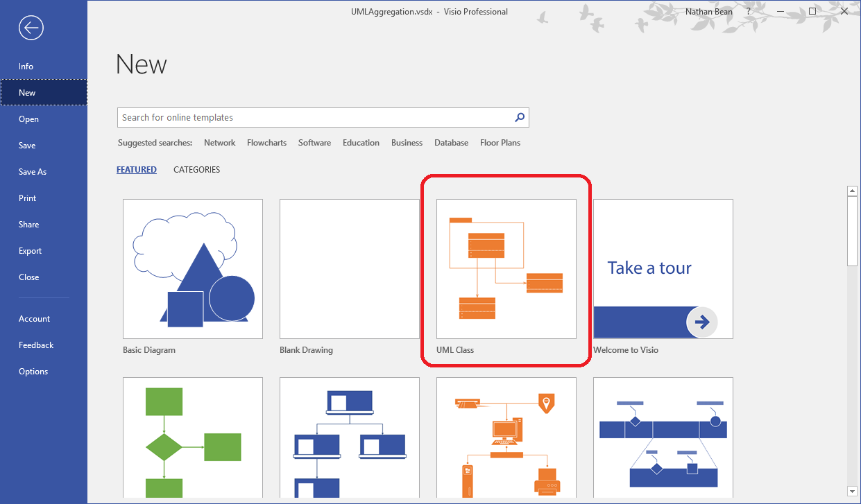
One of the many tools we can use to create UML diagrams is Microsoft Visio. For Kansas State University Computer Science students, this can be downloaded through your Azure Student Portal.
Visio is a vector graphics editor for creating flowcharts and diagrams. it comes preloaded with a UML class diagram template, which can be selected when creating a new file:
Class diagrams are built by dragging shapes from the shape toolbox onto the drawing surface. Notice that the shapes include classes, interfaces, enumerations, and all the associations we have discussed. Once in the drawing surface, these can be resized and edited.
Right-clicking on an association will open a context menu, allowing you to turn on multiplicities. These can be edited by double-clicking on them. Unneeded multiplicities can be deleted.
To export a Visio project in PDF or other form, choose the “Export” option from the file menu.
In this section, we learned about UML class diagrams, a language-agnostic approach to visualizing the structure of an object-oriented software system. We saw how individual classes are represented by boxes divided into three compartments; the first for the identity of the class, the second for its attributes, and the third for its operators. We learned that italics are used to indicate abstract classes and operators, and underlining static classes, attributes, and operators.
We also saw how associations between classes can be represented by arrows with specific characteristics, and examined four of these in detail: aggregation, composition, generalization, and realization. We also learned how multiplicities can show the number of instances involved in these associations.
Finally, we saw how C# classes, interfaces, and enumerations are modeled using UML. We saw how the stereotype can be used to indicate language-specific features like C# properties. We also looked at creating UML Class diagrams using Microsoft Visio.