Chapter 2
The Waterfall Model
Go With the Flow
Go With the Flow
The waterfall model of software development breaks the process of creating software into discrete phases, as seen in this diagram:
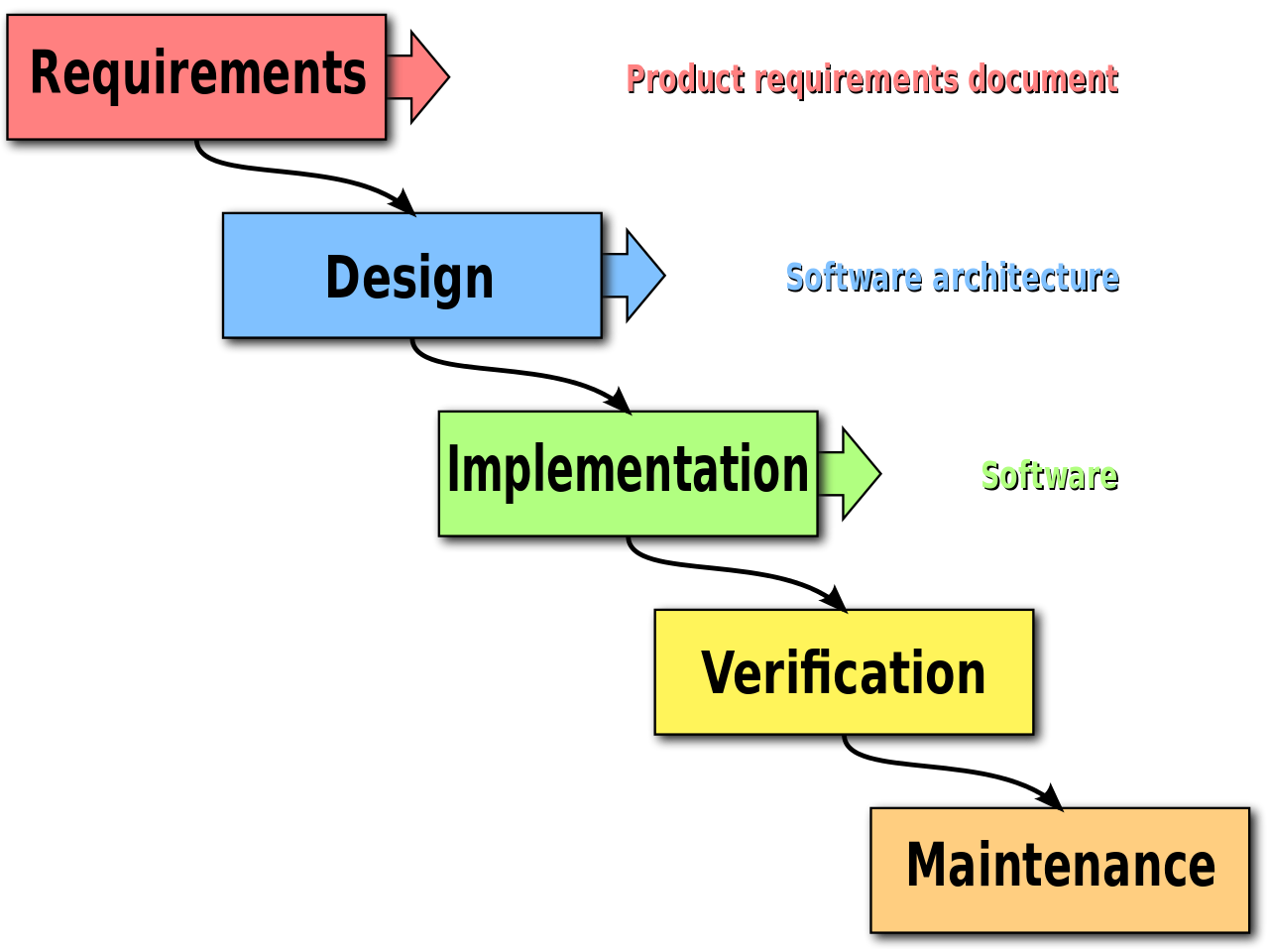
The phases correspond to specific steps that must be carried out to create the software:
This approach is based on engineering practices, and is more or less the strategy employed by NASA on the Apollo project. We’ll spend the next few sections exploring the individual phases in detail, and then discuss how widely adopted the waterfall approach is, as well as its strengths and weaknesses.
But what does it do?
The first step in any kind of software development project should be to determine what the software needs to do. In order to determine that, we need to fully understand the problem. This is the core of what requirements gathering is about.
Think back to the story problems from your early days of math:
If a train leaves station A heading west at 66 miles per hour, and a second train leaves station B at 44 miles per hour, when will they meet?
How would you solve this problem?
You really can’t - not without gathering more information. How far apart are the stations? Did the trains leave the station at the same time? What direction is the second train heading? Are they even on the same track?
The need to thoroughly understand the problem holds true for software development as well. If you begin building a project before you understand what it needs to do, you are setting yourself up for failure. Think back to your early days as a computer science student - did you ever start programming a project without reading the full assignment description? And did you ever find when you did read the last parts of that assignment, the program you had been writing was incompatable with those requirements?
Some key terms to learn in this chapter are:
When gathering requirements for designing a large software system, it is common to find yourself ending up with a lot of potential requirements. It is useful to organize these in some formal fashion, as it makes it far easier to find the right requirements for the right point in the design phase. It also can make it easier to determine if you’ve missed any potentially important requirements.
So what exactly is a requirement? To put it succinctly, a requirement is:
A capability that a product must possess to satisfy a customer need or objective
A requirement can also be thought of as a key component of the software as a business product. This is how your managers, marketers, and your contract likely think of it. To them, a requirement is something that your company has agreed to furnish in the final software product.
For you and your software development team, they serve a slightly different purpose. They help you to define what the goals of your development will be, as well as helping to define the scope of your project. Finally, they provide an objective way to measure the success of a project - either the final software meets the requirement, or it doesn’t.
As the previous discussion suggests, requirements can be categorized into business requirements and functional requirements.
Business requirements tend to be high-level, and express the requirement in terms that the customers and business professionals understand. These will typically be the requirements that are bundled into contractual agreements as well.
An example of a business requirement might be “The online sales platform must collect sales tax information and provide reports to the accountants on that sales tax.”
Functional requirements are typically drawn from these business requirements and provide greater detail, ideally enough detail for the developers to implement the full requirement. This often includes details beyond what the customer may think to provide - a part of parsing business requirements is therefore investigating the implications of those requirements.
For example, Kansas has 105 counties, each possessing their own sales tax rates. State law requires that any online sales made by a Kansas company to a customer in Kansas must charge sales tax according to the sales tax rate of the combined rates of the state, county, and city the item is shipped to (this is known as destination sourcing). All tax receipts are remitted (sent) to the State on an annual, quarterly, monthly, or pre-paid basis. 1
Thus, the functional requirements for this software built for a Kansas company might be:
By following the business requirement to its functional requirements, new business requirements can be suggested as well. Continuing from the example, the Kansas Department of Revenue accepts digital ST-36 submissions. It make sense to integrate the submission process directly into this software, as it will simplify reporting for the company, and avoid needing to purchase separate software to do so, or have accountants spend additional time preparing a ST-36.
Similarily, it might make sense to get the sales tax rates directly from the State of Kansas. The state does provide APIs for doing so at https://www.ksrevenue.org/atrl.html. Thus, the functional requirements could be re-written as:
Clearly, one further requirement needs to be determined - what specific remitting period is to be used (or if all need to be supported).
Hopefully this example helps you understand the importance of requirements gathering. If this requirement had not been thoroughly investigated, the developers may have assumed the system that only needed to collect sales tax at a single rate. Such a misinformed assumption would have led to much lower estimates of the amount of time and manpower needed to develop the feature, and this underestimate would have been used to develop the contracted completion dates.
When it was discovered that the system built in this way would not met the customer’s needs, changes would have to be made. These changes would be expensive, and who was responsible for paying that extra expense could become a point of contention. Further, it may be very difficult to integrate the idea of destination-based sourcing into the near-complete project, leading to throwing away large portions of progress.
Clearly, requirements gathering is crucial to the success of a software project!
Kansas Department of Revenue, “Kansas Sales Tax and Compensating Use Tax”, Rev 6-20. ↩︎
There are typically non-functional requirements in every software development project as well. These aren’t captured in the software we are developing, but inform our choices of platform, language, and approach.
Non-functional requirements commonly include:
The hardware that will be available for the software to run on. This might be determined by what the customer already has, or they may be intending to purchase new hardware - in which case the software developers may be able to make recommendations.
Other software this software could work with or integrate into. This may include the software already used by the customer (i.e. in our example, the customer’s accounting software might be able to accept sales data directly, instead of requiring accountants to manually transfer it)
The necessary performance of the software, i.e. how quickly the software will need to process data or how many users it will have. A good example of a performance requirement comes from the Healthcare.gov launch - the developers expected 50,000 to 60,000 thousand simultaneous users, but at launch over 250,000 attempted to sign up - nearly five times the anticipated load.
Usability - making sure the software is usable by a diverse audience - is unfortunately often an overlooked aspect of software development. Consider the common use of red and green to indicate good and bad status. About 8.5% of all people are red-green colorblind, and cannot distinguish between these two colors! Using secondary indicators (i.e. icons with colored messages) and using different hues of red and green (so there is a perceived shade difference) are simple steps that can be taken to make sure the software communicates effectively to this audience.
Cultural sensitivity requirements can take many forms in software development. For example, the user interfaces we design may rely on metaphors that only hold for our culture and appear idiosyncratic for other cultures. The terminology we use in software can also carry cultural implications - the common terms “whitelisting” and “blacklisting” carry undertones of systemic racism, for example, as do “master” and “slave”.
Bias can also creep in other ways as well. For example, most facial recognition software works best for white male faces, and returns more false positives and negatives for people of color. Considering the current makeup of the software development industry, currently 66% White (non-Hispanic) and 20% Asian (Non-Hispanic), leaving only 14% of programmers from other racial and ethnic groups. 1 So when programmers working on facial recognition software needed quick test subjects, who did they use? Themselves of course, and in doing so, implicitly focused their algorithms on recognizing people who looked like them.
Availibilty refers to internet hosted/supported applications, and how often they are allowed to be ‘down’. Consider Amazon.com, which durning the 2020 lockdown was making $10,000 in sales every second while facing its highest loads ever. 2 One hour of downtime would cost the retailer 36 million dollars!. On the other hand, designing for limited downtime brings additional technical challenges, like supporting hot swapping in both the infrastructure hardware and the software.
Reliability refers to the frequency of error conditions. It may not be a big deal for your text editor to occasionally crash. But for the control code in a pacemaker or the autopilot in a commercial jetliner, error conditions can be life-threatening.
Maintainability refers to the ease with which bugs are fixed and new features are added to a program. There is little software developed today that will not see new releases for the purpose of minor updates and bug fixes, let alone new major versions.
Extensibility also refers to the ease with which new features are added to a program, but the mechanisms by which this is done are different. With maintainability the features are added as part of the core software. With extensibility, these are typically done externally to the core code, through plugins or by accessing an API (application programming interface). This allows the system to be expanded, sometimes by third parties, without needing to replace the existing software installation.
Security refers to how well-protected the program’s function and data are from malicious agents (both human and software-based). Programs that handle sensitive information typically need higher levels of security. The prevalence of Internet connectivity in modern life means that programs are no longer running in an isolated environment - even simple desktop applications need to pay attention to security risks!
Data USA, “Computer Programmers”, 2020. ↩︎
Irana Ivanova, “Amazon makes $10,000 per second as shoppers shelter in place”, CBS News, May 1 2020. ↩︎
Features are another way of describing software, and often get confused with requirements. A feature is a way of describing the software, and tends to be quite high-level. In this sense they are much like a business requirement, but without the focus on the business side of the need.
Usually, a feature is tied to multiple requirements, i.e. a feature might be:
The business requirements derived from this might be:
And the functional requirements would drill into each of those requirements, describing details the designers would need to know to design the software:
You can see in this example how a simple feature expands in detail as you move from business requirements into functional requirements. You also probably also note that in carrying out this process, you will likely need to return to your customers for clarification of their business processes and specific needs.
Similarly, this process suggests non-functional requirements. To take purchases, for example, we must process credit cards, which implies we’ll need to integrate with a credit card processing service. Additionally, if gifts are able to be sent up to a year after purchase, we’ll need warehousing facilities for storing purchased gifts, and additional software to trigger the shipping process at the appropriate time.
A final challenge in discovering requirements is that your customers may not do a great job of telling them to you. We sometimes describe requirements as falling into one of three categories:
The conscious requirements are those your customer is aware of; correspondingly, they’re the easiest to gather because the customer shares them.
In contrast, unconscious requirements are those that are so deeply ingrained in the way the customer thinks and works that it doesn’t even occur to them that someone not involved in their work would not see it. A common example is units of measurement - a nurse or doctor thinks in terms of cc’s (cubic centimeters) as the default unit of volume whereas most of us might use tablespoons, cups, or fluid ounces.
This is why it is important for requirements gatherers to spend significant time with customers, ideally following them through their daily work processes - to see with ‘outside eyes’ the process they engage in. This is very similar to observation methods used in the field of anthropology - a few elective courses in that field will make you a far better requirements gatherer.
Finally, undreamed requirements are those that the user hasn’t even imagined. Most often, this category consists of things we could do because we are writing software and the technologies we can integrate into it, of which the typical user is unaware.
For example, one of the more common software development tasks is to take a process that used paper forms and translate it into software. Must customers will describe their needs as a one-to-one translation of the paper process into a digital one. But there usually are lots of opportunities for making the process more efficient by linking data in ways that isn’t possible for a paper process… sharing these opportunities is a great way to ensure you are making software that improves the lives of your customers!
There are many techniques used to gather requirements, which vary in their formality and approach.
Most requirement gathering begins with working with the stakeholders of the software project - those individuals who will be using or impacted by the software. It is important to remember to include all stakeholders - there is a common mistake made where the requirements gathers focus on the requirements identified by a select group of stakeholders, and ignore the others.
A good example of this error comes from a local company, GTM, who manufactures custom embroidered and screen-printed sports uniforms and T-shirts. During a period of intense growth, they contracted with a software developer to create a custom software solution to manage their workflow.
The developers focused on requirements drawn from the artists, sales, and management staff, and neglected to visit the factory floor. The resulting software worked well for taking orders, but failed in aspects related to the actual manufacturing and shipping work.
Embroiderers, for example, had to visit a single terminal in the factory to get a project number from the new system, then visit another legacy terminal on the other side of the factory floor to retrieve the embroidery program corresponding to that project. Issues with how the program reported shipping instructions to the shipping floor likewise resulted in long shipping delays and lost orders.
These issues were eventually addressed, but impacted GTM’s sales, ability to ship orders in a timely fashion, and ultimately impacted their reputation with their customers.
In working with these stakeholders, it is common to employ formal methods adopted from the social sciences. Formal methods are systematic in their application and when applied well can provide a clear picture of complex interactions and ideas. These methods include:
A good resource for K-State students for exploring these formal social science methods is the SAGE Qualitative Research Methods book, available in electronic form from the K-State Library.
Not all projects involve building a solution to a known problem - sometimes the point is to create something unique and (hopefully) desirable. For this kind of project, approaches borrowed from research and design may be more appropriate. These approaches can also be used to address unknown aspects of a more traditional problem-solving software project. These can include:
Along with the risk of failing to address the needs of a group of stakeholders, another common challenge in requirements gathering is to understand that different parties in the development process have different ways of looking at the project and the requirements, which can cause issues down the road.
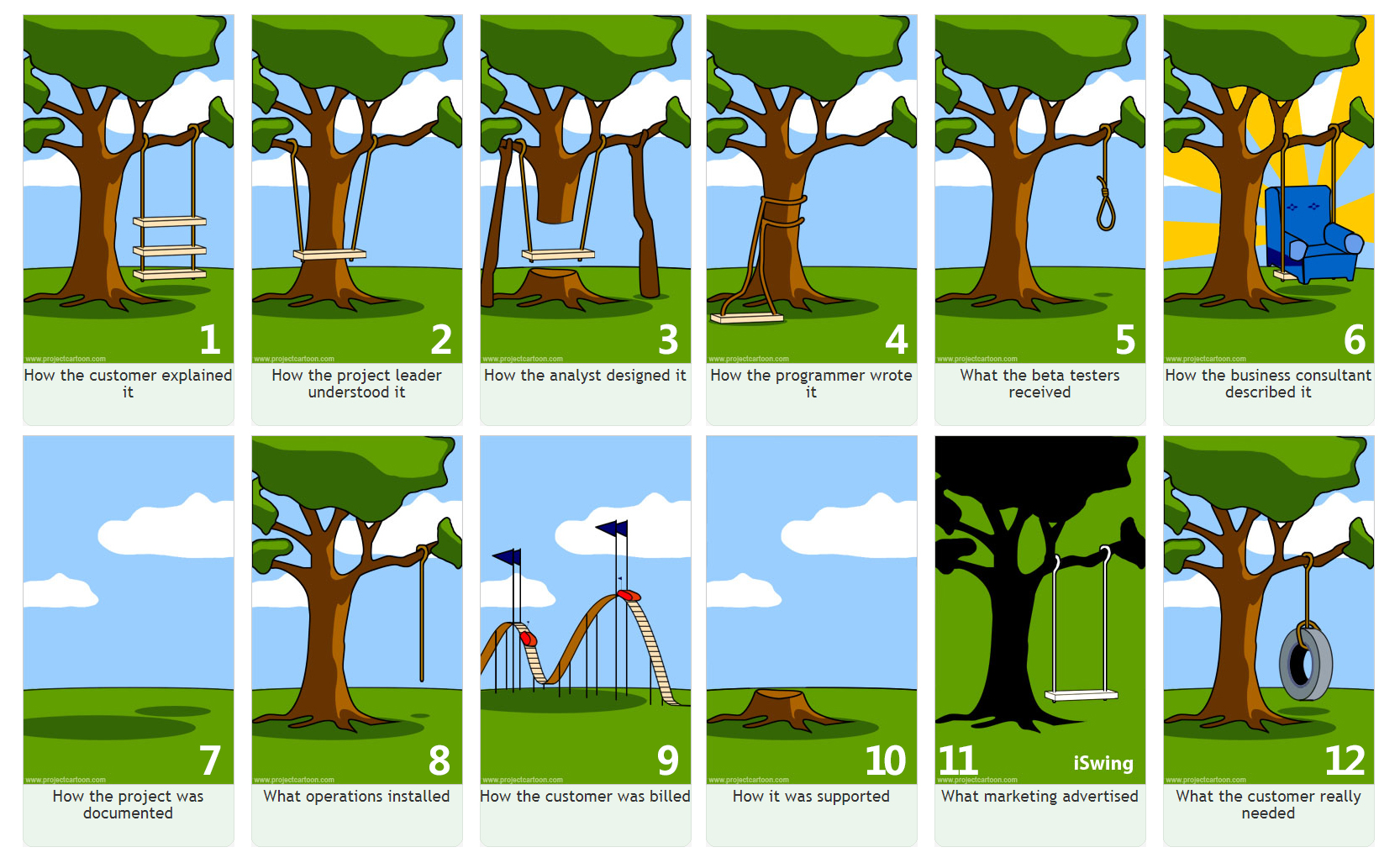
Consider the Tree Swing cartoon, a classic humorous graphical metaphor for communication challenges arising from the different backgrounds of participants in a project:
As a software developer, you need to both learn to recognize the viewpoints of your stakeholders and respond to them appropriately and professionally. These skills are best developed through practice, so be sure to try to see the project from your stakeholder’s perspective!
Requirements gathering sets the stage for the rest of the waterfall process, and is critical for understanding the needs an scope of the program you will be developing. This process begins with obtaining business requirements from the customer, and should include input from all stakeholders. This information is gathered through formal information-gathering processes borrowed from the social sciences.
These business requirements should be broken down into functional requirements fine-grained enough to give the developers a clear picture of what the software will need to accomplish. Moreover, they need to be comprehensive enough to not leave developers with unanswered questions. For novel functional requirements prototyping and brainstorming can be useful in sussing out possible implementation approaches and their feasibility.
The outcome of this process is a comprehensive document detailing the requirements of the software. It will commonly include sketches of proposed user interfaces and a discussion of how the software will integrate with other systems. It is also common to identify priorities of the various requirements.
You may be wondering, if this model of software engineering was so widely adopted, why did so many software projects continue to fail? Of course, some development houses never adopted a formal model, and rather continued in cowboy coding practices. But there were also many flaws in how the waterfall model was commonly adopted.
The ability to divide labor amongst the different phases was a boon from a business perspective, but it came with challenges. One of the largest is communication. It was necessary for each different team to convey complex ideas to the next group in the chain, and this did not always go smoothly. The cartoon below is based on the tree swing metaphor, which makes the point that each specialization has its own way of looking at and describing a project. If the different teams can’t converge on a shared reality, problems are sure to ensue.
A second problem with the division of labor cropped up as it became more and more difficult to find and hire qualified programmers. If you consider the different phases, the only phase you really must have experienced programmers is in creating the design. As long as your implementers could follow the details of the design and built their little piece following the specification, the software could be created. So the inexperienced programmers were often shifted to implementation jobs, and testing was instead handed off to much cheaper non-programmers. Similarily, the requirements gathers did not necessarily need to be programmers, and social scientists, advertising, and business majors all had the skills to effectively talk with customers. And they were also cheaper. Finally, the maintenance phase became a convenient dumping ground for those programmers who were ineffective at development jobs - i.e. those who couldn’t design or follow a plan.
A third problem was that with this division of labor, it often made more sense to reassign a team once they’d finished a phase to a new project. So the team working on the next phase would find it far more difficult to effectively communicate with the team responsible for the phase before. Questions that weren’t covered in
As the non-programmers did not have the right vocabulary or understanding of computer systems to communicate effectively with the actual system designers, the previously mentioned communication issues often grew worse. And because the requirements gatherers didn’t really understand software development, they often missed important details or asked the wrong questions (that’s not to say that programmers in that role don’t often ).
Let’s come up with a plan!
The second step in any kind of software development project should be to develop a plan of how the software should be built - ideally before any code is written. This is what design is all about. This is also the antithesis to cowboy coding which is likely how you learned to program. Working on a software system without a clear plan lies at the heart of many software project failures.
This section will examine in detail how such plans are developed and documented.
Some key terms in this chapter are:
The outcome of the design phase is a design document. It provides a design, or specification, for a software system. You can think of it like an architect’s blueprints provide the details for construction tradesmen to build a building - it provides rich enough direction that skilled laborers can follow in carrying out their portion of the work. In the waterfall model, the design document fulfills a similar role - it allows the work of building a software system to be broken down and assigned to different programmers focusing on a specific aspect of the system. If they follow the specification in the design, then the code created by each of these programmers works cohesively to create a viable program.
On the other hand, if the document lacks sufficient detail, or the programmers disregard aspects of the design and substitute their own ideas, the overall program will be compromised. Returning to the building metaphor, one of the classrooms in our department was originally built with the projection screen deploying over the exit door - a clear case of either 1) lack of detail in the plans, or 2) an installer not following them.
As you can imagine, a design document can grow quite large. To help combat this, Unified Modeling Language (UML) and other modeling approaches have been developed to convey design aspects visually, allowing the text of the document to focus on conveying key details. You’ve already worked with many UML diagrams and specifications in your education - most of your early programming assignments were essentially specifications. We’ll review those (and possibly introduce a few more) next.
To put it succinctly, a UML Class Diagram represents the classes and the associations between the classes in an object-oriented program. Each class is represented by a separate box, and the associations between classes by arrows. The intent of the class diagram is to represent the complete structure (but not behavior) of an object-oriented program. This allows individual programmers to focus only a small part of the overall program - a class and the classes it has associations with. Combined with the other information contained in the design document, the programmer can implement their piece of the program and it should ‘just work’ when combined with the code written by other programmers.
classDiagram
  Bear <|-- AnimatedBear
  class Bear{
    <<abstract>>
    +name string
    growl()* string
  }
  class AnimatedBear{
    +growl() string
    +dance()
}In a UML class diagram, visibility (public/protected/private) is specified with symbols:
The boxes representing a class are divided into three compartments. The first compartment displays the class identity, the second its attributes (fields), and the third its operations (methods).
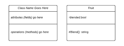
Each element in a compartment appears in its own line, and uses the format described below.
The class identity is its name (again, capitalization matters). We can optionally preface it with a visibility symbol (if unmarked, we assume public). If the class is abstract, it should be italicized, and if it is static, it should be underlined.
The attributes represent the state of the objects, i.e. its variables. These may use different names based on what programming language you are modeling (i.e. fields, properties, instance variables), but if it holds state, this is where it goes. These are represented by typed elements using the pattern:
$$[visibility] name : type [constraint]$$The optional $[visibility]$ details the visibility of the element using the symbols described above.
The $name$ is the element’s name, and should be exact (i.e. capitalization matters). If the element is abstract, its name should be italicized. If it is static, the name should be underlined.
The $type$ is the element’s type (i.e. float/int/bool).
Finally, the $[constraint]$ any optional constraints, expressed in a pair of curly braces after the element.
For example:
$$+ weight: int \{weight: >= 0\}$$Indicates a public field named weight of type int whose value should be zero or greater.
The operators represent the behavior of the object, i.e. its methods. These are specified using the format:
$$visibility name([parameter list]) : [return type]$$The $visibility$ details the visibility of the operator (i.e. public/private/protected). Visibility is expressed using symbols described above.
The $name$ is the operator’s name, and should be exact (i.e. capitalization matters). If the operator is abstract, its name should be italicized. If it is static, the name should be underlined.
The $[parameter list]$ is a comma-delineated list of operators in the form:
$$name: type$$Finally, the $[return type]$ is the element’s type (i.e. float/int/bool). If it can be omitted if the return type is void or undefined.
The association (the relationship) between classes are specified by arrows between the class boxes. The format of the arrow, along with its direction, conveys details about the association.
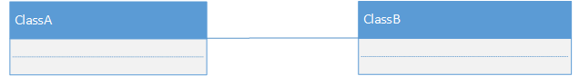
Associations are classified as being has-a or is-a and weak or strong. The four combinations are therefore:
| Association | Type | Representation |
|---|---|---|
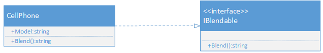
| Realization | weak is-a | dashed arrow |
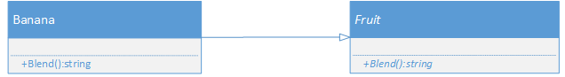
| Generalization | strong is-a | solid arrow |
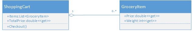
| Aggregation | weak has-a | open diamond fletching |
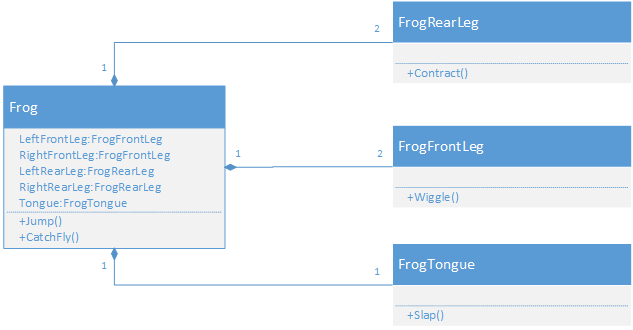
| Composition | strong has-a | filled diamond fletching |
The arrow is always in the direction of the relationship, i.e. from the class that has-a instance of the other class to that class, and from the class that is-a instance of another class to that class.
Realization makes an interface or abstract class “real” by implementing its methods. We call this weak because the interface or abstract class does not provide functionality to the implementing class.
Generalization refers to extracting the parts that classes have in common and “generalizing” them into a base class. You probably know this relationship as inheritance. We call this a strong relationship because the base class provides functionality to the derived class.
Aggregation refers to one class holding references to another one - i.e. through a field of that type, or a collection of that type. It is a weak association because the object the aggregated object or objects can be swapped for other instances (or left null).
Composition also refers to one class holding references to another one. The difference is that with composition, those other object instances are typically created at the same time as the containing object, and are never swapped out for other instances. You can think of the whole group as a single object, even though it is multiple separate ones.
UML was intended to represent a generic object-oriented language. However, it was recognized that many languages have specific features not found in others. To allow UML to represent these, it also includes the idea of stereotypes - specifying language-specific features using a pair of angled brackets:
$$\langle\langle stereotype \rangle\rangle$$For example, in C# properties are accessor methods (a get and/or set) which are treated as fields. We can represent this by applying a stereotype to a field, i.e.:
$$+Count:int \langle\langle get \rangle\rangle$$Indicates the property Count has a get but no set method.
You can learn more about UML class diagrams by reviewing the CIS 400 textbook, visiting the official UML website, or by reading some of the textbooks in the O'Riley For Higher Education library.
Most production applications today utilize structured data that is commonly stored using a specialized application known as a database. For traditional relational databases, a number of modeling approaches have been developed, including UML database diagrams, Entity Relationship diagrams, and Crows-foot notation. The purposes behind these modeling approaches is similar to that of the UML Class Diagram - a database model allows its readers to 1) quickly set up the database structure and 2) understand how to access the needed information (i.e. how to author SQL queries to obtain the needed data).
This also means that the database design can be done by a separate team than the one building the program that will making use of the database. Thus, the structure of the database can be developed by experts in database design with an eye towards efficient modeling, storage and information retrieval, while the actual programmers using the database only need to be able to write queries. If the necessary queries are identified as stored procedures as part of the design document, then even less knowledge is needed on the part of the programmers - the stored procedures can be written by the database architects, and the programmers only need to know how to call them.
You can review database diagrams by reviewing chapters 9 and 10 in the CC 520 textbook, visiting the official UML website, or by reading some of the textbooks in the O'Riley For Higher Education library.
A UX (for user experience, aka user interface) diagram visually presents what the user sees on the screen of a device running the program in a simplified form. These are also sometimes called wireframes (due to the diagram typically only showing text and outlines of controls) or bluelines (a term borrowed from architecture, where plans are drawn in blue pencil before begin printed in black and white). Typically, each screen of the user interface is drawn as a UX diagram, along with a description of the purpose of the controls on the page.
In addition to displaying individual screens in a UX, arrows can be added connecting screens to represent how the program’s state advances based on user interaction. The actions the user takes are typically used as a label for these arrows. Increasingly, UX modeling applications are employed to provide an interactive ‘click-through’ experience of the app, though most of these tools will also print a traditional diagram form.
UX diagrams provide several benefits. While most customers won’t understand other aspects of the design document, a UX diagram represents the part of the program they will be interacting with. Accordingly, this is the portion of the design they will be able to give the most feedback for - and that feedback may influence other aspects of the design. Second, to design a good UX, a developer must understand the customers’ needs and way of thinking about a problem – essentially, they must be familiar with the customers’ processes and discipline. With a good UX diagram, however, this understanding is not vital. As long as the UX designer understood the customers’ needs and captured it in the UX diagram, the user interface it specifies will make sense to the customer. The programmer need only implement it.
We can build it!
The implementation phase of the waterfall should be the most familiar to you, as it is the actual process of creating the proposed software system. This is, after all, the subject of most of your early coursework - the basics of programming, algorithm design, and considering time and memory complexity of your employed algorithms.
It is critical that the implementation adhere to the details provided by the design, as this ensures that a large body of programmers can work independently on the aspects of the system. But despite the best efforts of the designers, it is not uncommon for some critical details to be overlooked. In a properly implemented waterfall process, this kind of “splashback” is anticipated, and a process exists for proposing, approving, and disseminating changes to the design. Because these changes can cause problems for the other programmers working in other areas of the software, it is important for the change to be communicated clearly to all parties (hence the need for a formal process).
In addition to following the design, programmers in this phase should be applying best practices in terms of documenting the code they write as well as writing automated tests. This effort ensures that the code not only meets the specification, but that it works as intended, and is straightforward to maintain. Remember, the programmers working with the project during its maintainence phase will likely not be those who created it in the first place.
Implementation work takes place in a development environment - traditionally, a powerful PC with extra tools (compilers, code editors, debuggers, etc) installed. Moreover, the compiler/interpreter is typically run in a debug mode throughout the development process, which injects extra tooling into the compiled/interpreted program to allow for the display of debug information (i.e. giving memory state at breakpoints, etc.). While this makes for a more powerful and speedier development process, there are some implications to keep in mind:
This project will contain the following features:
devcontainer.json// For format details, see https://aka.ms/devcontainer.json. For config options, see the
// README at: https://github.com/devcontainers/templates/tree/main/src/javascript-node
{
"name": "Node.js, Vue 3 & MySQL", //
// Or use a Dockerfile or Docker Compose file. More info: https://containers.dev/guide/dockerfile
// "image": "mcr.microsoft.com/devcontainers/javascript-node:1-22-bookworm"
"dockerComposeFile": "docker-compose.yml",
"service": "app",
"workspaceFolder": "/workspaces/${localWorkspaceFolderBasename}",
// Features to add to the dev container. More info: https://containers.dev/features.
"features": {
"ghcr.io/devcontainers-contrib/features/vue-cli:2": {}
},
// Use 'forwardPorts' to make a list of ports inside the container available locally.
"forwardPorts": [3001],
// Use 'postCreateCommand' to run commands after the container is created.
"postCreateCommand": "cd server && npm install && cd ../client && npm install",
// Configure tool-specific properties.
"customizations": {
"vscode": {
"extensions": [
"Vue.volar"
]
}
}
// Uncomment to connect as root instead. More info: https://aka.ms/dev-containers-non-root.
// "remoteUser": "root"
}This can be easily customized to support different frontends or backends by adding different features or customizations. Also note the forwarded port 3001 can be changed.
docker-compose.ymlversion: '3.8'
services:
app:
build:
context: .
dockerfile: Dockerfile
volumes:
- ../..:/workspaces:cached
# Overrides default command so things don't shut down after the process ends.
command: sleep infinity
# Additional Services
mysqlnvd:
image: mysql:lts
container_name: mysqlnvd
environment:
MYSQL_HOST: mysqlnvd
MYSQL_DATABASE: database
MYSQL_USER: user
MYSQL_PASSWORD: password
MYSQL_RANDOM_ROOT_PASSWORD: fact
phpmyadminnvd:
image: phpmyadmin:latest
container_name: phpmyadminnvd
environment:
PMA_ARBITRARY: 1
ports:
- '8080:80'Likewise, the additional services defined in this file can be updated to include things like Mongo, PostgreSQL, or other Docker containers. If your system has a reverse proxy such as Traefik, you can add the labels here to enable external routing.
DockerfileFROM mcr.microsoft.com/devcontainers/javascript-node:22-bookwormIf addtional items should be included in the container they can be added here. For example, I typically install zsh (my preferred terminal), gnupg (to sign commits), npm-check-updates (to easily update npm packages) and better-commits (to create more useful commit messages).
FROM mcr.microsoft.com/devcontainers/javascript-node:22-bookworm

# [Optional] Uncomment this section to install additional OS packages.
RUN apt-get update && export DEBIAN_FRONTEND=noninteractive \
    && apt-get -y install --no-install-recommends gnupg2 zsh

# [Optional] Install global node modules
RUN su node -c "npm install -g npm-check-updates better-commits"server and client projects yet, so running npm install in those folders will not work.server and client Projectsserver folder.nodemon and configure a dev command in the package.json file to use nodemon with this setup..gitignore file in the server folder. I recommend using this one as a starter.create-vue scaffolding tool to create a Vue 3 project in the client folder.vite only attaches to internal ports and uses a random port. I recommend customizing the dev script in the package.json file to match include explicit host and port entries: "dev": "vite --host 0.0.0.0 --port 3001"vite project, customize the vite.config.js to proxy API connections to the backend as desired. See that file in this repo for an example..vscode/tasks.json with the following content:// .vscode/tasks.json
{
// See https://go.microsoft.com/fwlink/?LinkId=733558
// for the documentation about the tasks.json format
"version": "2.0.0",
"tasks": [
{
"label": "Watch Server",
"type": "shell",
"command": "cd server && npm run dev",
"group": "build",
"presentation": {
"group": "buildGroup",
"reveal": "always",
"panel": "new",
"echo": false
}
},
{
"label": "Watch Client",
"type": "shell",
"command": "cd client && npm run dev",
"group": "build",
"presentation": {
"group": "buildGroup",
"reveal": "always",
"panel": "new",
"echo": false
}
},
{
"label": "Watch All",
"dependsOn": [
"Watch Server",
"Watch Client"
],
"group": "build",
"runOptions": {
"runOn": "folderOpen"
}
},
]
}This will add a Watch All task to the tasks that can be found in the command palette under the Run Task option. It will also automatically run both tasks when the VS Code window is opened in the future.
docker-compose.yml file to log in to the database.This project includes a small modification in the default Vue project to query data from the /api/ route in the Express backend project to demonstrate using vite to proxy connections from the frontend to the backend.
This project DOES NOT include appropriate Docker configurations for deployment. DO NOT USE the dev container Dockerfile for deployment.
I can follow up with a proper deployment setup if desired - contact me!
