Bits and Boolean Algebra

For this lesson, we’re going to be talking primarily about Boolean logic, Boolean algebra and how that plays into computer science and the foundations of how important that is and the role it plays and what we do. So before we get started, and before we can talk about things such as Boolean logic, we need to know where it came from. That leads us to Aristotle, way back in the 300 BC, as you may know, right Aristotle is one of the fathers of modern philosophy and logic among many other things. He studied under Plato, who himself was taught by Socrates and was also the teacher of Alexander the Great, so pretty much affected the entire world of Western philosophy that came after him. One of his major contributions was this idea of using formal logic to prove a point, then this form of logic, also known as Aristotelian logic, a point is proven based off of a series of premises.
For example, in this form of logic, we can present a series of facts. And so our premise here in that sense, all humans are mortal. Socrates is human. Each one of these is a fact and pretty easily proven to be true. Now, under Aristotelian we can use these use this premise to then prove a new fact. So if all humans are mortal, which is true, and Socrates is a human, which is also true, we can also prove or conclude that Socrates is also a mortal.
If we skip ahead a few thousand years later, we come to George Boole. In 1854, he published a book called An Investigation of The Laws of Thought, in which he tried to apply the rapidly growing field of mathematics to the laws of logic. His goal was to reduce something as complex as logic to simple mathematical equations. And with the right rules in place, even a complex logic Statement could be completely proved, or even disproved using the same algebraic techniques they used to understand other parts of the world.
And so if we take a look at an example, our same style of facts that we had before now transcribed into something that is more easily represented in algebra or mathematics, so for example, if we take are all humans are mortal and Socrates is a human, we can map that to different variables. And you can kind of imagine different kinds of facts being transcribed here where we can substitute proven facts or true facts in places of a and b and c, we can conclude new facts or new premises or new things from that. So if A and B so the upside down would be their means and we’ll talk about that here in just a little bit. But if both A and B are true, and B and C are true, we can conclude that A and C is true. Since A and B are true, B and C are true, then A and C must also be true. But this translation is somewhat flawed but we can leave that for a later course in logic or philosophy to describe why …but let’s take a deeper dive into what each of these mean so primarily Boolean operators Boolean values and what that means for Boolean logic.
As you know from the reading computers operate primarily using only binary values so ones and zeros and Boolean logic and Boolean algebra operate off of true and false principles or yes no answers but that in itself is a binary decision there is no in between. So we can easily translate binary and Boolean logic back and forth. Commonly speaking, one is going to mean true and zero is going to mean false. Now, this is the same thing is translated in a variety of other contexts, like electrical systems where a on or off signals being produced one or on meaning electrical current, or off or zero. meaning no electrical current. So while these are traditional representations in many electrical and programming contexts, these values can be reversed for a variety of reasons. And really the moral of the story here is make sure you know which one you’re working on.
Let’s take a look at what the Boolean and operator does out in this Venn diagram here we’re going to kind of use these to showcase where the Boolean statements that we’re checking out with the Boolean operator where these statements are actually evaluated to be true. So if we assume that we are two facts here, A and B are both true. So let’s say this inner circle here, this left circle here represents a and this right circle here represents B and the square on the outside represents everything else. So when a and b are not, so if A and B are both true, then the statement evaluates to true. So the left hand side and the right hand side of the operator both must be true in order for the whole statement to be true. If A is false, or B is true. false, then the whole thing would be false. Now if we introduce a third fact, see, we kind of get the same results, right. So similar kind of story with the Venn diagram. Here we have a, b, and c. But notice that this little square here where we were actually filled in over here is no longer filled in. And that’s because all three facts must be true for the whole statement to evaluate to true. So a has to be true, B has to be true. And C has to be true in order for the whole statement to evaluate true.
So we’ll have similar representation here for the OR operator where the English word is the representation in Python of the OR operator the double bar symbol, so this is just the two vertical bars from your keyboard that is the OR operator in Java, C sharp and other programming languages and then a capital V is great. To be the OR operator for Boolean algebra. So let’s take a look at how or operates. So if we have the same statement, as we have before the same two premises A and B both being true initially, and the circles are kind of the representation of the same thing here, but the OR operator will evaluate to be true if either side of the operator are true. So if the left hand side is true, or the right hand side is true, the whole thing will be true. So if A is true, or B is true, so left hand side and the right hand side, so if A or B is true, then the whole statement is also true. And so nothing on the outside will actually be filled in quite yet. And the similar kind of story is for a third fact or fifth, that one has to be true for the whole statement to be true. So if any of them are true, the whole thing is true, but things kind of get tricky when we’re in introduce this next operator the exclusive OR exclusive or you won’t really find normally in programming languages. The Exclusive OR can be simulated using and or and the next operator that we’ll be covering here in just a second.
But the exclusive OR works in a little bit of a different way than the regular or the exclusive OR operates very similar to what we would expect the normal or operator to be in the sense that if A is true, or B is true, the statement is true, but notice that a and b is now false. If a and b are both true, the statement is false. So the exclusive OR operator is expecting one or the other. So that means the left side or the right side must be true, but not both. That is where the exclusive portion of the exclusive OR or the X or operator actually comes out. If I introduce a third fact things get to be a little bit more difficult to understand because now I would expect it to be kind of similar pattern as we have up here just to be, or on my just with my two facts, everything in the middle would be white, but everything on the outside would be red. But you notice when when we have all three to be true, all three can be true and the exclusive OR would still be true. Now let’s take a look at why that would be the case.
So let’s take a look at the example that we saw on the slides. We have our facts a, and our XOR operator. So we have a XOR B XOR. See, now if we kind of do our substitutions here now we could substitute ones and zeros here are true and false. So let’s go ahead and substitute our Boolean values here for our variables. So if A is true So we have a XOR B, which is also true. And C, which is also true. Now, just like most of your math problems, even when you’re just doing multiplication and division, you’re always going to evaluate your statement from the left to the right. So we need to first evaluates true x or true now XOR Exclusive OR exclusive right, the left or the right can be true, but not both. Since the left hand side of my operation is true, and the right hand side of my operator is true, this portion of the statement evaluates to false. Then all we need to do then is keep on working the rest of our statements. So we still have one XOR left. So we have false x or true? Now exclusive or one side or the other must be true but not both. So false x or true is actually true because both sides aren’t true. So this statement you say a false x or true, evaluates to true. So the whole thing true x our true, false XOR true, ends up being true.
So our last Boolean operator here is the NOT operator. The NOT operator acts pretty much like negation, as you would expect, like multiplying something by negative one not something is the opposite of what it actually is in Python as the previous Boolean operators the and and the OR operator, the NOT operator in Python is very English light not but Python is kind of weird. You will also see the exclamation point In some operations, but it doesn’t mean the traditional knots or negation operator as in many other programming languages. So, again, you’ll see not in Python, the exclamation point, this is going to be things like Java. And the weird sideways l here, this is going to be your Boolean algebra. So let’s take a look at what the Boolean operator not actually looks like. As I mentioned, the NOT operator is a negation, so not something as the opposite. So not a or not true is false. So not a if I write a here, so everything in the circle is a so when A is actually true, so everything inside of the circle then everything on the outside of a is actually true because it’s negated and similar idea for B when B is true, everything But B is true. So the whole statement is evaluated as such and similar idea if I introduce a third fact. So if I have three facts A, B and C, not B means that everything but B is true, just like in this example here.
So with all these new tools, we needed some new algebraic rules to really deal with them. Thankfully, most of the rules you know, apply quite well, but there’s one rule that needed to be added. In mathematics. When you multiply by negative one, you have to change the signs. Similarly, Augustus DeMorgan came up with a way to deal with the negation of entire Boolean logic statements. So this becomes very similar to how you multiply a statement or a regular mathematical statement by a negative one. I guess system marking came up with a way to deal with the negation of entire Boolean logic statements. The DeMorgan’s theorem essentially states to treat the NOT operator like the negative sign so you’re going to apply the negative to each of the premises or facts and then swap the operators or basically and become or’s and or’s become hands. So let’s take a look at an example. So if we invert our particular statement here where we have a and b, right, so A and B, not a and b becomes not a or not B, so we negated or applied the knot to a and the knots to b and the knot and becomes or similar idea for or not a or b becomes not a, and not B.
Now, in Boolean algebra, just like when you multiply by a negative one, a lot of the similar rules apply and Boolean algebra just like they do in mathematics. So in general, the OR operator works very much like the plus operator not works very much like negation, like we’ve already seen, and works very much like multiplication.
The associative property, also Hold. So we have a and b, and c becomes a and b and c. So if I made the substitutions here, just based off of what we had here, if we had one, and the AND operator works like multiplication, though times two, parentheses, substitute the multiplication symbol and for the end, and then we have three. That is the same thing as saying one times two times three.
The commutative property also holds. So again, let’s try to make some substitutions. A and B is the same thing as saying B and A. So that’s the same thing as saying. Two times three is the same thing as Three times two.
And the distributive property also holds. So A and B or C is the same thing as saying a and b, or a and c. So let’s make our substitutions again, let’s substitute again, one four a, so one times to remember, or is like the addition operator plus three is the same thing as saying, we’re going to kind of distribute right as we normally would with math, distribute the one across two plus three. So one times two plus three is the same thing as saying one times two, plus one times three. So we distributed the Want across and we’ll end up with the same exact result. Same idea or Boolean logic if we make each one of these properties, as we seen here, and mathematics applies and works directly with Boolean algebra. So what this really helps you as when you start working with Boolean logic, even when programming you can actually use these properties to simplify a lot of your Boolean logic statements to make them easier to read and easier to program.
With the new tools from Boole and DeMorgan, others began to see where they could be applied in the real world. In 1886, Charles Sanders Peirce noted in a letter that logical operations could be easily simulated by electrical switches. Many others worked on the idea too many to name here, but 51 years later.
In 1937, something happened. In 1937, Claude Shannon, a 21 year old graduate student at MIT was working on this same idea. He wrote a master’s thesis that some of called the most important master’s thesis of all time, titled a symbolic analysis of relay and switching circuits. In it, he showed that you could use electrical switches in Boolean algebra to construct circuits that could show any logical OR numerical relationship that you wanted. It’s available free online and will be linked in Canvas and linked in this video as well if you’re interested, but this is really cool. Kind of what was the gateway to electrical circuits, all of the cell phones and computers and electronic devices that you use today, this was the initial theory behind how all of those devices actually work.
So underneath Claude Shannon’s representation as far as translating Boolean algebra and Boolean logic into electrical circuits, we also needed a new representation for that this new representation is called logical gates. So it’s basically the same setup as we had with Boolean algebra and is very similar to if we have a and b, this is equivalent to this right where our two inputs are coming in on these two lines here are the AND operator it’s like a D, and then our output is the line leaving from the operator. similar idea for or so this is a or b we have XOR a XOR B, and not so this is same thing as saying that. Now really with the knot, the really important part is this little knot or this little mini circle at the end here and also note right that all of our Boolean operators here are compound operators, meaning that we have a left hand side and a right hand side, but the NOT operator only has one input. So one fact so just keep that in mind. But we can also apply the NOT operator to all of our other operators as well. So we can have NAND, nor, and x nor a little.at. The end here on the output is really the only part that matters for negating the result of a operation and and or XOR. One of the interesting things though, that it’s really kind of come out of the representation of Boolean logic on electrical circuits. So The work done by Claude Shannon and will continue part of this work and future lectures as well.
But one of the really interesting things that have kind of come out of this is the idea of a universal logic gate. The idea here is that any electrical circuit can be finished off by just using NAND gates. So all the complex Boolean logic that we could ever think of so any logical statements that we could write in Boolean algebra or Boolean logic can be redone with just using NAND gates or NAND operators, which is a pretty interesting thing and really why this is so important is that it greatly increases the speed efficiency and decreases the cost of manufacturing electrical parts.
Let’s go through an example of some Boolean logic now that we’ve covered some of the operators and some of the rules that govern the Boolean algebra behind it. A lot of times what you’ll see in computer science, especially when you’re dealing with Boolean logic and complex algorithms, our truth tables, truth tables showcase all the different options for each Boolean variable inside of a Boolean logic statement, as well as what output those particular facts for those variables actually produce. So let’s take a look at an example that we’ve already kind of done with end. So we’ve already explored the statement A and B, and C. You’ve already seen what the Venn diagram for that looks like, but we can also explore what that looks like again here in just a second, but let’s take a look at all possible values that we could actually input for A, B, and C. And if you remember, we’re only going to have two values binary values, either one, or zero or true or false. Now, both work synonymously. And you’ll find both in truth tables. And in fact, what the examples that you’ll be working with, we actually do use ones and zeros for true and false. So if you remember one means true, zero means false. But let’s take a look at how we can actually fill out our truth table here with those particular values. Now, I’m going to go ahead and use T for true and false. But as you could imagine, you could substitute one for true and zero for false and everything would be identical.
So what we would actually start with our truth table here as each of our columns here represent each of our variables or each of our facts as part of our Boolean logic statement though For a, what we’re actually going to do here, easy way to fill this out is we’re going to want to fill out all the different possibilities. So if we exhaustively go through each of our variables here, you may find that each one has two possible values. And then if we multiply this out, if it’s powers of two, we have eight possible outcomes or combinations of these values. You’ll notice that I have eight different rows in my truth table. That’s going to represent all of the different combinations that I actually have for this Boolean logic statement. Now generally, when we try to figure out how many different combinations we have the number of options we have for our variable to the power of the number of variables that we actually have, so that in this case would be two to the power of three. So two times, two times To write two times two is four times two is eight. This is the total number of possible combinations of truths or our facts that we actually could get out of this Boolean logic statement.
So let’s elaborate on that and fill out our truth table accordingly. The easiest way to start out for our truth table is go down one column first, because there’s kind of a general pattern that you can follow on filling this out. If we just fill half of our rows with false and then half of our rows with true we can work that out. So the column fills out pretty easily. This the pattern that you can kind of follow for the second column works as such, if you just fill in half of the falses, or half of the rows that was false of the first column with true and half of them with false and a similar pattern for the sets of trues down here. So if I make an imaginary line right here in the middle, we can try to fill out all the falses first. So, I want to fill out half of these with false and half of these with true. So let’s start with false first. So false, false, and then True, true. Down here, I’m going to do the same exact thing. false, false, true, true. And I’m going to continue the same pattern where I’m going to fill half of what I just filled in and see with falses, and half of what I just filled in with true. So for this set of falses, here, I’m going to have false true. With the set I’m going to have false true. Now, this pattern doesn’t exactly always hold, especially as you start adding a fourth column But with three variables, it’s pretty easy to fill out using this particular pattern. But if you find yourself filling out a truth table for more than three facts, all we’re actually doing is exhaustively writing out all of the different combinations of true and false values or each set of variables. Now, let’s go through and try to evaluate the output here, or our truth table. This particular statement is fairly easy with a and b, and c. Because we’ve already seen that with an and statement, both sides of the operator must be true for the whole statements to evaluate to true.
So in my output here, I’m going to write out what this set of facts this row of facts evaluates to for our Boolean logic statement up above. So I’m just going to kind of put row numbers here 123. And then let’s write our output. Over here, so, false and false and false, is going to evaluate to false because no sides are true and similar ID here, false and false is false. And true. is also False. False and true is False. False and False. False and true. And notice I’m evaluating this from left to right, right, because my statement is a and b, and c, so I’m evaluating the A and B first, and then I’m adding that result with C. So false and true is False. False and true is false. true and false is false, false and false is false. true and false is false, false and true is false. True and true is true. But true and false is false. True and true is true, true and true is true. Now on our truth table, we have a completed evaluation of what our Boolean logic statement A and B and C can actually cover, right, so we have all the different combinations of values, or truth of A, B, and C. And then we’ve also evaluated those truth values as part of our output. So now we know when this statement is true, and when the statement is false.
In lecture in the previous video, we saw what the AND operator looked like for our Venn diagram as well. So let’s kind of draw that over here, just so we kind of have what that looks like again, and or the statement just as we kind of had over in our truth table, we’re only going to fill in the spot where a true B is true and C is true, where essentially that means the output of our country table is true. So if I just kind of put a, b and c here, and then we also remember, we have a square on the outside that represents everything that is not A, B, or C. I will be giving you some more examples of this or where I’m going to actually give you the truth table, then you’re going to try to generate the Boolean logic statement and the Venn diagram and even some logic gates.
But let’s try to draw the logic gates for this as well. And the examples that you’ll be doing our logic gates are written like this. So we have our three inputs A, B, and C. Now if you remember the logic gate for and looks like this. Let’s draw that. So what we want to do is start out by drawing the logic gate for the first part. Have the logical statement, which is a and b. So to do that, you can kind of imagine electrical wires kind of coming off of the sources of A and B, or your individual variable. So I’m going to draw kind of a little wire out over here into my open space on the right from a and then my second input to that statement is B. So I’m going to draw a wire out from there. And I’m going to draw my gate. So it looks like a D, and my output there. Now I can draw the second part of the statement, which is and C. So I’m going to draw a line from C and draw out here and it’s okay if your wires go at a 90 degree angle or a little bit of a curved connect the logic gates together. And now that I have the output from a and b, and the output the input from C, we’re going to join those together with another and gate. So the logic gate drawing of a and b and c can be viewed as that. Now everything that I just did apart from generating your truth table are going to be reviewed and practice in a few examples.
In this video, Carrie Anne shares the principals of binary numbers and how we use Boolean Algebra to work with binary values. We get to see the truth tables for the basic statements (or, and, not, xor) as well as their respective logic gates. We also get a good primer for working on more complex statements.
CrashCourse. “Boolean Logic & Logic Gates: Crash Course Computer Science #3 “. Mar, 8, 2017. YouTube. Available: https://www.youtube.com/watch?v=gI-qXk7XojA
So let’s take a look at example one. And the best way to start this is where the output is actually true. So if we examine this line here, this line and this line, we can see that when B and C are true, output is True. When a and c are true, the output is True, or when all three are true, the output is also true. So a really good way to start is just by coloring in these three facts.
So when B and C are true, that’s this little square here. Then when a and c are true, that’s this little portion of the Venn diagram. And then when a, b, and c are so when all three are true, And that’s this little center part of the diagram. And then all other rows of the truth table are all false or zero. So we’re not going to fill in anything else in the Venn diagram here. So this is the full output of or the full expression represented as a Venn diagram.
So let’s tackle this as a Boolean expression. And so we’ve already talked through parts of what the Boolean expression would actually be. So this can start here with a and c, when a and c are true, the statement is true. So let’s write a and see us as one portion of our Boolean expression. So I’m going to write that using parentheses, and then we have B and C. So I’m going to kind of write this over here, B and C. What that’s the other part of the truth in our Boolean expression, but we can’t just write them side by side, right, we need to join the middle because we also need the center portion. So it’s either a and c are true, or either A and C or B and C. So enter a or operate in between. So if A and C are true, or B and C are true, so that’s this portion right here. So when a and c, or B and C are true, and our expression is true, this will represent our Boolean logical statement. But there are alternative ways to write this. And these aren’t just the only ways another way you could have wrote this would be C, right? Because in all three cases, C is always true. So C, and a or b.
So let’s take a look at what the logic gates look like. So the logic gates and I’m going to write the logic gates for my top statement here. So this one right here, we need to write the left and right hand side of the OR operator first, and the OR operator is going to join these two at the end. The lines here represent the inputs of A, B and C. So I’m going to draw out the input of a because in this case, we have a and c. And those are connected together with the AND operator. And that gives an output and we have the same thing with B and C. So we have B, C, those are both connected together with an AND operator and both of those are joined together using or. So this would be the logic gate for this particular statement here.
Let’s do a bit of a deeper dive into that worked example to explain some of the nuances working with Boolean Logic Expressions, Truth Tables, Venn Diagrams, and the connections between those three. Unfortunately, this is not well explained or covered elsewhere in online resources, but we find that it is really helpful to revisit these concepts here before the end of this module.
This is a lot of conceptual information to digest at once. However, we don’t expect you to become proficient in this right away! This is just meant to be an introduction to the concept of Boolean Logic and Boolean Algebra, which you’ll become more comfortable with over time as you practice your programming skills and take later classes in Computer Science.
For now, we just want to introduce the topic and give you a chance to try it out in the quiz at the end of this module. If you don’t do well on the quiz, don’t sweat it!
This material is handy if you want to review the concepts or get in some practice, but the best way to learn is to just keep doing examples and practicing as you learn to code.
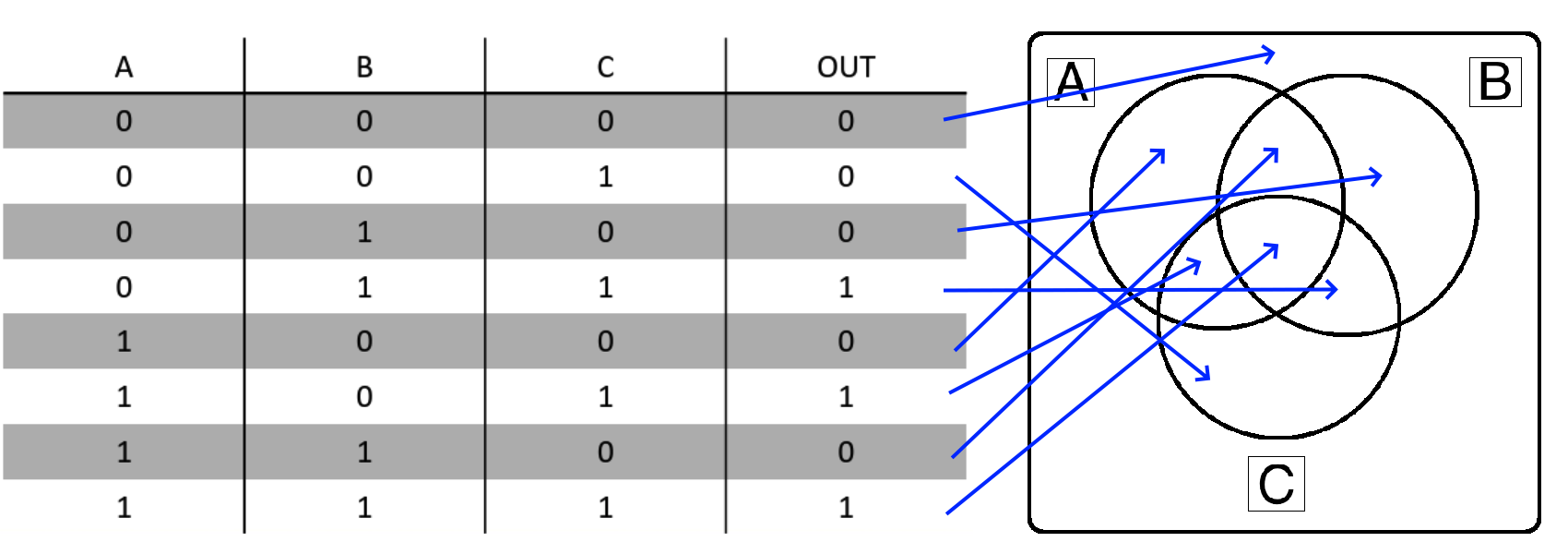
When working with Truth Tables and Venn Diagrams, the key idea to remember is that each line in the Truth Table corresponds to exactly one space in the Venn Diagram.
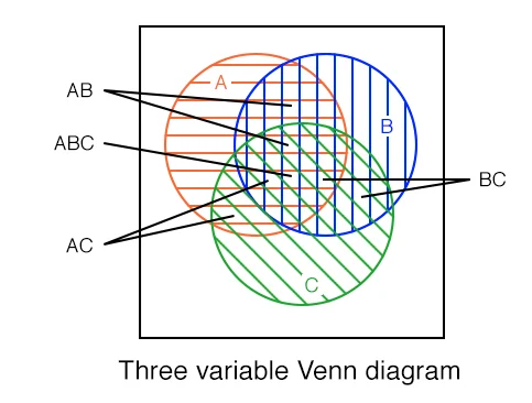
Each labelled section in the Venn Diagram above corresponds to the variables that are True or 1 in the corresponding Truth Table. We can even draw arrows directly from each line in the Truth Table for Example 1 to the Venn Diagram:
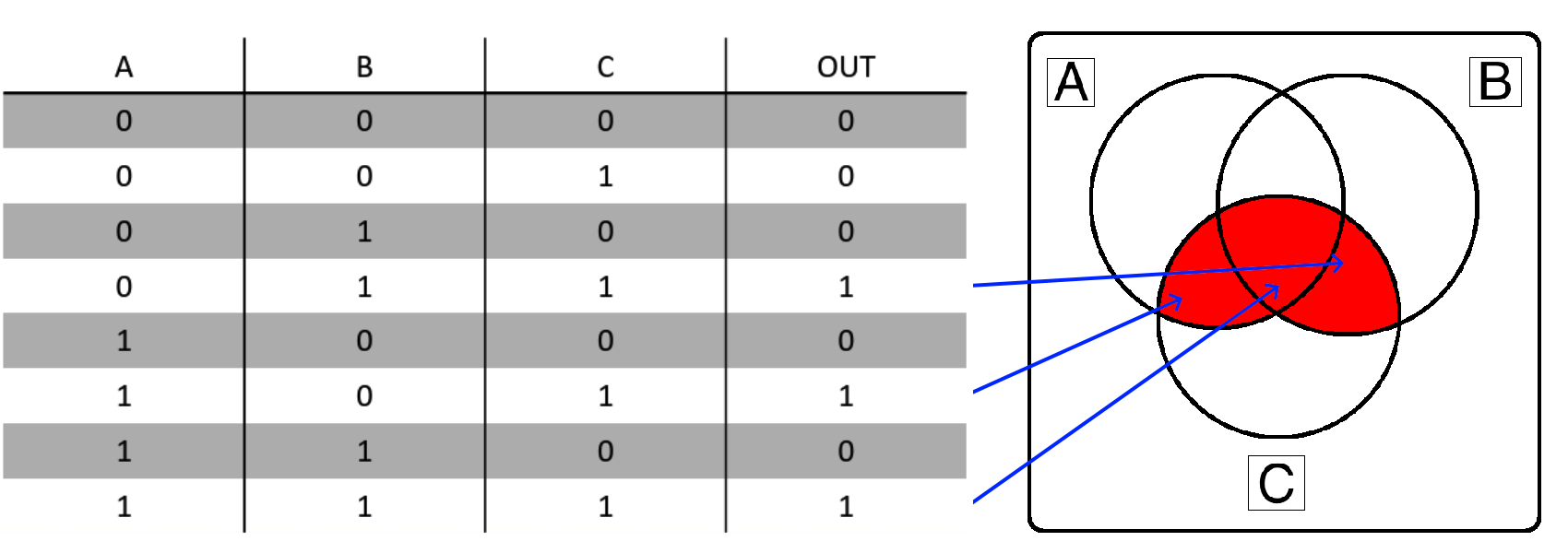
So, if the “OUT” column in the truth table is True or 1, that section of the Venn Diagram becomes shaded and is part of the desired output. Therefore, if you have a Venn Diagram or Truth Table, the conversion between the two is a direct one-to-one connection. Here’s what that looks like for Example 1:
Once we understand either the Truth Table or Venn Diagram for a desired Boolean Logic expression, we can use that information to start building the Boolean Logic expression itself. This can be done in one of three ways:
So, let’s go through these three methods and see how they relate.
Let’s start by directly converting the information in our Truth Table and Venn Diagram to individual Boolean Logic terms. To do this, look at each row in the Venn Diagram where the “OUT” column is 1. Then, for each variable in that row, we either include it in the term directly if it is a True or 1 in the input, or else we include it with a NOT symbol ($\neg$) before the variable if it is a False or 0 in the input. We must include these false variables in our terms, or else we would get different results (i.e. $A \wedge B$ is not the same as $A \wedge B \wedge \neg C$)
So, we would end up with these three terms from our truth table above:
Finally, our full Boolean Expression using these three terms would combine them using the OR ($\vee$) symbol. This is because the “OUT” column in the Truth Table is True or 1 if any one or more of these terms are True. So, our resulting Boolean Expression at this point would be the following:
$$ (\neg A \wedge B \wedge C) \vee (A \wedge \neg B \wedge C) \vee (A \wedge B \wedge C) $$
At this point, we can stop if we don’t care about reducing the expression to simpler terms. So, once again, there is a direct one-to-one translation from either a Truth Table or Venn Diagram to a Boolean Logic expression that is in this form. In fact, this form is known as the Disjunctive Normal Form of a Boolean Logic expression (though it is not the reduced form). A great way to remember this form is that it is an OR of ANDs (the individual terms are all AND operators, and then the terms are combined using OR operators).
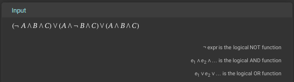
Before we go any further, we can check our work by entering this formula into Wolfram Alpha and checking the Venn Diagram and Truth Table it produces and make sure they match our original setup. While it is possible to enter all of the fancy Boolean Logic symbols into Wolfram Alpha (it does understand them), it is often easiest to just convert them to their English counterparts as shown below:
(NOT A AND B AND C) OR (A AND NOT B AND C) OR (A AND B AND C)You can also click this link to go directly to Wolfram Alpha with this input provided.
First, we can check that our input is parsed correctly since it matches our Boolean Logic expression at the top:
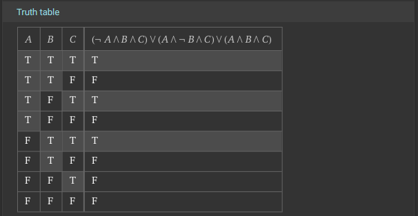
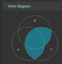
We can also look at the Truth Table and Venn Diagrams further down:
Notice that the Truth Table is ordered a bit differently than what we see above (it is reversed), and the Venn Diagram is rotated a bit, but hopefully it becomes pretty clear that we have a match! So, our translation from the Truth Table to a Boolean Logic Expression is valid!
Once we have a valid Boolean Logic Expression, we can use the laws of Boolean Algebra to reduce it. We cover some of these laws earlier in this chapter, but Wikipedia has a good listing of them as well. We’ll refer to the laws as they are described in Wikipedia as we perform these operations.
First, it is often very helpful to remember that, in many cases, AND ($\wedge$) can be treated similar to multiplication ($\times$), while OR ($\vee$) can be treated like addition ($+$). So, in some fields (such as computer engineering), it is common to rewrite the statement above like this:
$$ (\neg A B C) \vee (A \neg B C) \vee (A B C) $$
This may make some operations more intuitive, especially where we are “factoring out” or “distributing” a term by applying the Distributivity laws. So, we’ll use this modified notation while performing our Boolean Algebra reductions.
Unfortunately, reducing this expression is actually a bit complex, because there is not an obvious starting place. Instead, what we need to do first is duplicate a term by applying the inverse of the Idempotence of $\vee$ law. This law states that $ x \vee x = x $, so we can invert it by replacing any single term $x$ with two instances of the term that are connected with the OR ($\vee$) operator. We’ll do this to the last term in the expression for now:
$$ (\neg A B C) \vee (A \neg B C) \vee (A B C) \vee (A B C) $$
Next, we want to group some similar terms together to make later operations a bit more obvious. So, we’ll apply the Commutativity of $\vee$ law to rearrange the terms, and also use the Associativity of $\vee$ law to group some terms together:
$$ \Big( (\neg A B C) \vee (A B C) \Big) \vee \Big( (A \neg B C)\vee (A B C) \Big) $$
Now we can start to simplify things a bit. In both groups of terms, we notice that they each share the variable $C$, so we can apply the inverse of the Distributivity of $\wedge$ over $\vee$ law to “factor out” that term. Notice that this is very similar to how we can apply a similar law in ordinary algebra:
$$ \Big( C \wedge \big((\neg A B) \vee (A B) \big) \Big) \vee \Big( C \wedge \big( (A \neg B)\vee (A B) \big) \Big) $$
After that, we’ll see that the first pair of remaining terms shares the variable B, while the second pair of terms shares the variable A. So, we can once again apply the Distributivity of $\wedge$ over $\vee$ law to “factor out” those shared terms in each pair:
$$ \Big( C \wedge \big(B \wedge (\neg A \vee A) \big) \Big) \vee \Big( C \wedge \big(A \wedge (\neg B \vee B) \big) \Big) $$
Now we can start to remove some terms. The Complementation 2 law in Wikipedia states that $x \vee \neg x = 1$, which means that we can replace a term and the inverse of that term connected with an OR ($\vee$) operator with the value True or 1. We’ll do this for both $A$ and $B$ terms:
$$ \Big( C \wedge \big(B \wedge 1 \big) \Big) \vee \Big( C \wedge \big(A \wedge 1 \big) \Big) $$
Next, we can use the Identity for $\wedge$ law, which states that $x \wedge 1 = x$, to effectively remove those True or 1 terms from the statement. Again, remember that in regular algebra, we would know that the term $1A$ would be equivalent to just $A$, so if we rewrite $A \wedge 1$ as just $1A$ and then just $A$, it feels very logical!
$$ ( C B ) \vee ( C A ) $$
Finally, if desired, we can apply the Distributivity of $\wedge$ over $\vee$ law one more time to “factor out” the $C$ variable again:
$$ C \wedge (B \vee A) $$
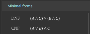
There we go! Both of those reductions are valid minimal forms of the Boolean Logic Expression. Once again, we can go back to Wolfram Alpha to check our work:
In that screenshot, we can see both the minimal Disjunctive Normal Form (DNF) as well as the minimal Conjunctive Normal Form (CNF) for the expression.
Another great way to convert a Truth Table or Venn Diagram into a Boolean Logic Expression is to use a bit of intuition. The video earlier in this chapter showed one way to do this suing the Venn Diagram, but let’s use another method - using a concrete example!
For this example, let’s assume that we have been given the following rules:
We can build a Truth Table using these rules as shown below:
| Friends Over (A) | Sunny Outside (B) | Mom Says Yes (C) | Go Swimming |
|---|---|---|---|
| 0 | 0 | 0 | 0 |
| 0 | 0 | 1 | 0 |
| 0 | 1 | 0 | 0 |
| 0 | 1 | 1 | 1 |
| 1 | 0 | 0 | 0 |
| 1 | 0 | 1 | 1 |
| 1 | 1 | 0 | 0 |
| 1 | 1 | 1 | 1 |
Ahh! Notice that this Truth Table is identical to the Truth Table given in Example 1 shown above! We have created a set of rules that immediately generate the same Boolean Logic Expression that matches our example. It may take a little bit of thinking, and we have to state the rules very clearly, but generally we can always create a set of rules that clearly describe any Truth Table. In practice, we often are starting with a set of rules like this (in our specifications document), and we are trying to build a Boolean Logic Expression that we can use in our code as we implement those specifications in our program.
Now, let’s use a bit of intuition about those rules above to generate a Boolean Logic Expression. If we really want to go swimming, we’ll quickly realize that there are two main things that we need to have:
Look closely at those rules! Just by talking through the scenario, we have created a Boolean Logic expression. Let’s rewrite it:
Mom must say yes
AND(it must be sunny outsideORwe have to have friends over)
If we replace each part with the corresponding variable, we can find the corresponding statement:
$$ C \wedge (B \vee A) $$
A similar way to state the rules might be:
Once again, we can rewrite that a bit to make the Boolean Logic operators more obvious:
(Mom must say yes
ANDit must be sunny outside)OR(Mom must say yesANDwe have to have friends over)
Finally, we can replace those parts with variables to get the corresponding statement:
$$ (C \vee B) \wedge (C \vee A) $$
So, as we can see, applying a bit of intuition to a real-world example that creates the same situation can make it pretty easy to work out a simple Boolean Logic Expression from a Truth Table or Venn Diagram.
The third method would be to use a Karnaugh Map. We won’t go into this method in too much depth, but we’ll briefly show how it works. There are some great online resources to learn more about applying Karnaugh Maps in this context.
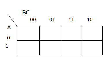
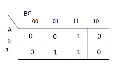
First, we’ll start with a blank 3 variable Karnaugh map. A Karnaugh Map is essentially a different way to structure a truth table by placing similar entries next to each other in a particular way:
Then, we’ll input the desired outputs from the Truth Table in each square of the Karnaugh Map:
Now, we’ll group connected terms. These groups can be either rectangular or square boxes. So, for this Karnaugh Map, there are two groups:
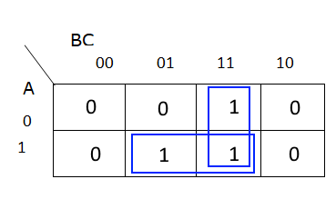
Finally, for each group, we identify the variables that don’t change within that group, and those become our terms. So, for the group in the bottom row, we see that both $A$ and $C$ are the same, but $B$ changes. So, one term we find is $AC$. For the group in the third column, we see that $B$ and $C$ are the same, but $A$ changes, so our other term is $BC$. Then, we combine those two terms together using the OR ($\vee$) operator to get this statement:
$$ (AC) \vee (BC) $$
There we go! That is once again one of our minimal Boolean Logic expressions found earlier.
Once clever things that we might notice is that there is also a one-to-one equivalence between Karnaugh Maps and Venn Diagrams. We know this since there is already a one-to-one equivalence between both of those and the original Truth Tables, so it is an easy assumption to make.
So, we can quickly see the arrangement of items in a Karnaugh Map and how they match up to our Venn Diagrams as shown below:
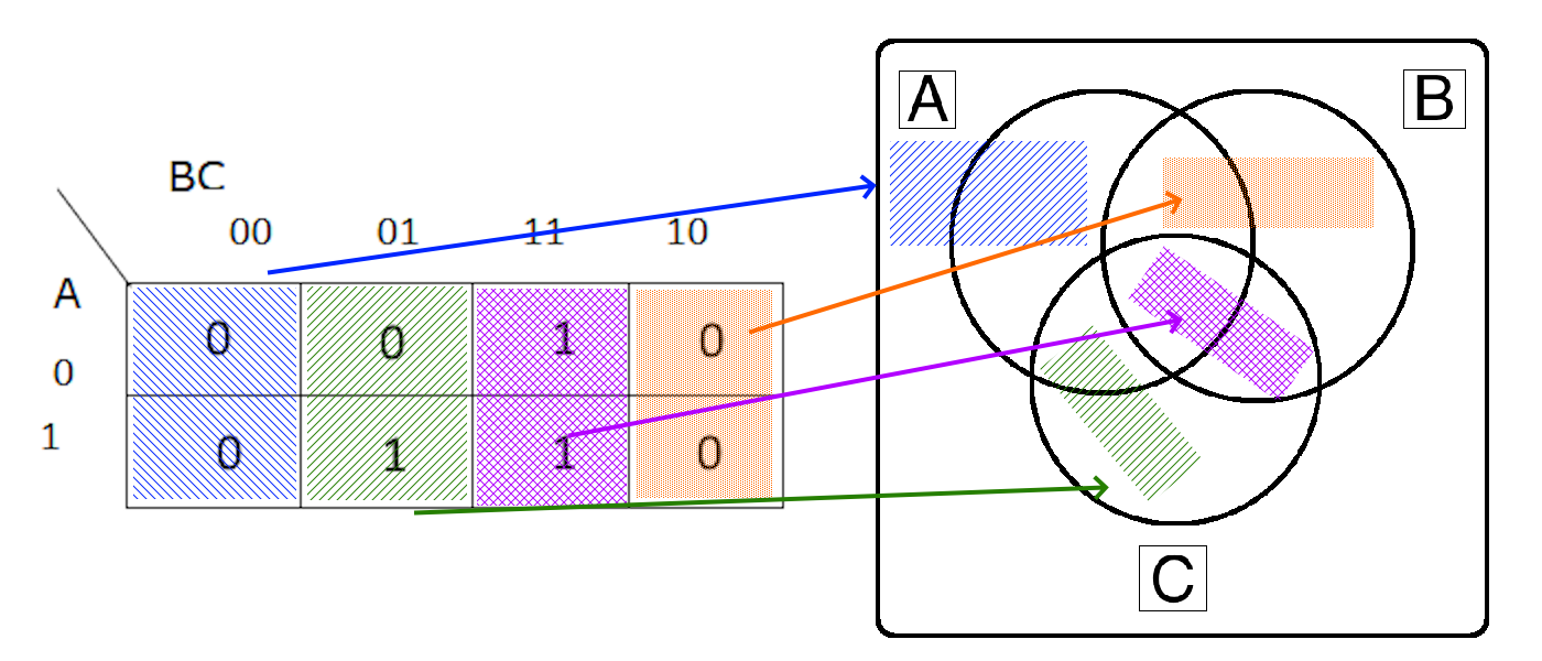
Notice that the the Venn Diagram has a very similar layout to the Karnaugh Map. This is because both of them are structured in a way for similar entries to be near each other. In fact, each time you cross over a line in a Venn Diagram, only a single variable changes value. The same works for a Karnaugh Map.
So, with a little intuition and an understanding how Karnaugh Maps work, we can perform a similar analysis directly on the Venn Diagram itself.
Why does all of this matter? Well, when we are trying to convert a real-world situation to code, it is often helpful (but not necessary) to be able to reduce our Boolean Logic expressions to simpler terms.
Let’s go back to the concrete example shown above. If we wanted to write a Python program for this, there are a few ways we could build it.
First, here’s what it would look like if we just directly encoded the rules as written:
# bool() returns False if the input is the number 0, otherwise True
# so we have to convert the string to an int first
sunny = bool(int(input("Is it sunny outside? (1 = yes, 0 = no)")))
friends = bool(int(input("Do you have friends over? (1 = yes, 0 = no)")))
mom = bool(int(input("Did Mom say yes? (1 = yes, 0 = no)")))

"""
Rules:
* If Mom says yes and it is sunny outside, we can go swimming even if we don't have friends over.
* If Mom says yes and we have friends over, we can go swimming even if it isn't sunny outside.
* If Mom says yes, we can go swimming if it is sunny outside and we have friends over.
"""

if (mom and sunny and not friends)
  or (mom and friends and not sunny)
  or (mom and friends and sunny):
    print("We can go swimming")
else:
    print("We cannot go swimming")
We could also use if-else statements instead of the or operator to achieve a similar effect:
if mom and sunny and not friends:
  print("We can go swimming")
else if mom and friends and not sunny:
  print("We can go swimming")
else if mom and friends and sunny:
  print("We can go swimming")
else:
  print("We cannot go swimming")
However, in both cases, these programs are more complex than they actually need to be, and it may make things more difficult to debug down the road. So, with a little intuition and the ability to reduce Boolean Logic expressions effectively (and correctly), we can simplify this code quite a bit:
if mom and (sunny or friends):
  print("We can go swimming")
else:
  print("We cannot go swimming")
Hopefully you can see the value in that much simpler program, both in terms of how easy it is to understand and debug, but possibly how much more efficient it is overall since it has fewer comparison to make.
Image Source: https://www.allaboutcircuits.com/textbook/digital/chpt-8/boolean-relationships-on-venn-diagrams/ ↩︎
Image Source: https://www.wolframalpha.com/input?i=%28NOT+A+AND+B+AND+C%29+OR+%28A+AND+NOT+B+AND+C%29+OR+%28A+AND+B+AND+C%29 ↩︎ ↩︎ ↩︎ ↩︎
Image source: https://www.learnelectronicswithme.com/2021/09/karnaugh-map-and-steps-to-solve.html ↩︎
Read Pattern on the Stone, Chapter 2.
“The Pattern on the Stone: The Simple Ideas that Make Computers Work” by W. Daniel Hillis. ISBN 046502596X, newer version is also available and will work fine