Basic 3D Rendering
It’s all triangles!

It’s all triangles!
The term “3D rendering” refers to converting a three-dimensional representation of a scene into a two-dimensional frame. While there are multiple ways to represent and render three-dimensional scenes (ray-tracing, voxels, etc.), games are dominated by a standardized technique supported by graphics card hardware. This approach is so ubiquitous that when we talk about 3D rendering in games, this is the approach we are typically referring to.
Remember that games are “real-time”, which means they must present a new frame every 1/30th of a second to create the illusion of motion. Thus, a 3D game must perform the conversion from 3D representation to 2D representation, plus update the game world, within that narrow span of time. To fully support monitors with higher refresh rates, this span may be cut further - 1/60th of a second for a 60-hertz refresh rate, or 1/120th of a second for a 120-hertz refresh rate. Further, to support VR goggles, the frame must be rendered twice, once from the perspective of each eye, which further halves the amount of time available for a single frame.
This need for speed is what has driven the adoption and evolution of graphics cards. The hardware of the graphics cards includes a graphics processing unit, a processor that has been optimized for the math needed to support this technique, and dedicated video memory, where the data needed to support 3D rendering is stored. The GPU operates in parallel with and semi-independently from the CPU - the game running on the CPU sends instructions to the GPU, which the GPU carries out. Like any multiprocessor program, care must be taken to avoid accessing shared memory (RAM or Video RAM) concurrently. This sharing of memory and transmission of instructions is facilitated by a low-level rendering library, typically DirectX or OpenGL.
MonoGame supports both, through different kinds of projects, and provides abstractions that provide a platform-independence layer, in the Xna.Framework.Graphics namespace. One important aspect of this layer is that it provides managed memory in conjunction with C#, which is a departure from most game programming (where the developer must manage their memory explicitly, allocating and de-allocating as needed).
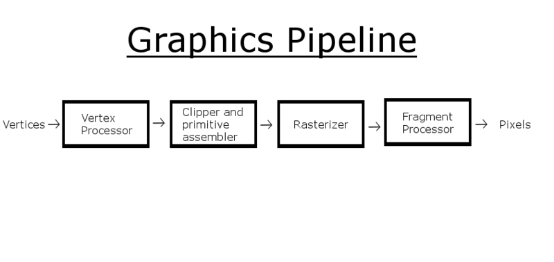
This process of rendering using 3D accelerated hardware is often described as the Graphics Pipeline:
We’ll walk through this process as we write a demonstration project that will render a rotating 3D cube. The starter code for this project can be found on GitHub.
You probably remember from our discussions of matrix math that we can create matrices to represent arbitrary transformations. Moreover, we can transform a vector by multiplying it by one of these transformation matrices. This is the mathematical foundations of hardware-accelerated 3D rendering. In fact, the GPU is nothing more than a processor optimized for performing matrix and vector operations.
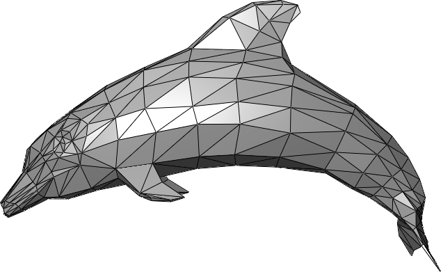
We model our three-dimensional worlds with triangles. Lots and lots of triangles. Why triangles? Remember that three points define a plane. Three points also can define a triangle. So we know that the three endpoints of a triangle will always be coplanar. If we used more than three points, there is a possibility that we might screw up and have one out-of-plane, which would break the process. So 3D rendering is almost entirely based on rendering triangles (you can also render lines and points with OpenGL and DirectX, but XNA only supports triangles and lines).
Complex objects are therefore composed of multiple triangles, which typically share sides and create a closed shape with a distinct inside and outside. We call these triangle meshes, and they effectively create a hollow shell in the shape of the object to be rendered:
Rather than creating structures for storing triangles, we store the endpoints of the triangles as vertices. These vertices are a data structure that (at a minimum) defines the coordinate of the triangle endpoint in three dimensions (A Vector3 in XNA). Vertices can contain additional data needed to render the mesh, including color, texture coordinates, and additional vectors like the surface normal (a Vector3 pointing out from the surface).
Let’s create a class to represent our cube, and give it an array of vertices that have both a position and a color:
/// <summary>
/// A class for rendering a single triangle
/// </summary>
public class Triangle
{
    /// <summary>
    /// The vertices of the triangle
    /// </summary>
    VertexPositionColor[] vertices;

}
Note the VertexPositionColor is defined in the Microsoft.Xna.Framework.Graphics namespace.
Triangles are then defined by the order the vertices are presented to the graphics card, defined by a graphics primitive type. There are four supported by XNA, and appear in the PrimitiveType enumeration. These are LineList, LineStrip, TriangleList, and TriangleStrip. The first two vertices in a LineList define the two endpoints of a line, the second two, a second line. In contrast, with a LineStrip each successive line connects to the previous one, sharing a vertex. Thus vertices 0 and 1 define the first line, vertices 1 and 2 define the second, vertices 2 and 3 the third, and so on…
The TriangleList and TriangleStrip work the same way. In a TriangleList each three vertices define a single triangle. Hence vertices 0, 1, and 2 define the first triangle, and vertices 3, 4, and 5, the second, and so on. With the TriangleStrip, vertices 0, 1, and 2 define the first triangle; vertices 1, 2, and 3 define the second, vertices 2, 3, and 4 the third, and so on…
Our Triangle will only be using vertices 0, 1, and 2, so either approach will be identical. Let’s go ahead and define those vertices in a helper method:
    /// <summary>
    /// Initializes the vertices of the triangle
    /// </summary>
    void InitializeVertices()
    {
        vertices = new VertexPositionColor[3];
        // vertex 0
        vertices[0].Position = new Vector3(0, 1, 0);
        vertices[0].Color = Color.Red;
        // vertex 1
        vertices[1].Position = new Vector3(1, 1, 0);
        vertices[1].Color = Color.Green;
        // vertex 2
        vertices[2].Position = new Vector3(1, 0, 0);
        vertices[2].Color = Color.Blue;
}One of the major innovations of hardware graphics has been the introduction of programmable shaders. A shader is simply a program that runs on a GPU, and performs some steps of the graphics pipeline. At the time XNA was created, there were three points in the graphics pipeline where programmable shaders could be inserted: the vertex shader, the geometry shader, and the pixel shader (additional shader points have been added to graphics cards since). These shaders are written in a language specific to the GPU and graphics library (DirectX or OpenGL). In XNA, this language is HLSL.
XNA seeks to simplify the details of setting up shaders by abstracting the heavy lifting into the Effect Class. An Effect handles configuring the graphics device to produce a specific effect through a combination of shaders and hardware settings. We can create custom classes derived from the Effect class, or use one of those already defined in XNA:
With our triangle, we’ll use the BasicEffect, which provides a basic rendering pipeline. Let’s add a field for one to our Triangle class:
    /// <summary>
    /// The effect to use rendering the triangle
    /// </summary>
    BasicEffect effect;
The effect also needs a reference to the GraphicsDevice held by our Game instance; so let’s also add a Game field:
    /// <summary>
    /// The game this triangle belongs to
    /// </summary>
    Game game;
You’ll also need to add the Microsoft.Xna.Framework namespace to make Game available.
Now let’s initialize our effects settings in a second helper method, InitializeEffect():
    /// <summary>
    /// Initializes the BasicEffect to render our triangle
    /// </summary>
    void InitializeEffect()
    {
        effect = new BasicEffect(game.GraphicsDevice);
        effect.World = Matrix.Identity;
        effect.View = Matrix.CreateLookAt(
            new Vector3(0, 0, 4), // The camera position
            new Vector3(0, 0, 0), // The camera target,
            Vector3.Up            // The camera up vector
        );
        effect.Projection = Matrix.CreatePerspectiveFieldOfView(
            MathHelper.PiOver4,                         // The field-of-view
            game.GraphicsDevice.Viewport.AspectRatio,   // The aspect ratio
            0.1f, // The near plane distance
            100.0f // The far plane distance
        );
        effect.VertexColorEnabled = true;
    }
There’s a lot going on here, so lets’ break it down.
The line effect.World = Matrix.Identity creates the world matrix. This matrix embodies a transformation that transforms our vertices from model space to game space. Consider our triangle - it has three endpoints (0, 1, 0), (1, 1, 0), and (1, 0, 0). As it is defined, it has one endpoint above the origin, one to the right, and the third is above and to the right - in line with the others. This is its model space. We might want it to appear somewhere else in our game world - say at (100, 100, 0). We call our game world world space, and a matrix that would embody the transformation needed to move our triangle from its model space coordinates to its world space coordinates is the world matrix. We’re using Matrix.Identity here, which won’t change those coordinates at all.
Instead of thinking of triangles, think of crates. We probably would use the same crate multiple times throughout our game. The crate would have been drawn in a modeling program, and probably had its origin at a corner or bottom corner (model space). When we put it into the level, we would translate and rotate it to get it in just the right spot (world space). We might put a second copy in a different location, with its own translation. Hence, the two instances would have the same model coordinates, but different transformations to place them in the world, embodied in different world matrices.
The line effect.View = Matrix.CreateLookAt(..) creates the view matrix. This is the transform that shifts us from world space into view space. View space is relative to the position of the observer - the eye (or camera) is at the origin (0, 0, 0), and they are looking along the z-axis. Since the observer exists somewhere in the game world, the view transformation shifts the coordinate system so that that position becomes the origin, and everything in the world moves along with it.
Matrix.CreateLookAt() is a method for creating a matrix to embody this transformation, and allows us to specify where the observer is looking from, and to. The first argument is the position of the observer - where the observer’s eye would be in the world. The second argument is a vector in the direction the observer is looking. The third helps orient the observer by defining which direction is up. Normally this would be the up vector (0, 1, 0), but if the observer was a plane that was executing a barrel roll, it would be the down vector (0, -1, 0) halfway through the roll, and every value between as the plane rolled.
The line effect.Projection = Matrix.CreatePerspectiveFieldOfView(...) creates the projection matrix. This is the matrix that transforms our 3D scene into a 2D one. It does this by setting z-values to 0 while (possibly) tweaking x- and y-values to create the illusion of perspective. There are two commonly used projections in video games: orthographic, which simply removes the z-values, flattening the scene; and perspective, which stretches distant objects an squishes near ones, creating the illusion of depth.
Matrix.CreatePerspectiveFieldOfView() creates a perspective matrix that accounts for the field of view of the observer. The first argument is an angle measuring how wide the field of view should be, measured in radians. Humans have approximately a 120 degree field-of-view, but most of this is peripheral vision, so we typically use smaller numbers. This can also be tweaked to provide the illusion of using a telescope or wide lens. The second argument is the aspect ratio - this should match the aspect ratio of the screen, or the result will seem distorted. For this reason we draw its value directly from the GraphicsDevice. The last two values are floats indicating the far and near planes. The near plane is how close objects can be to the observer before they won’t be rendered, and the far plan is how far away they can be.
Matrix.CreateOrthographic() creates an orthographic matrix. As there is no distortion, its arguments simply describe a cube, with the near plane and far plane composing the nearest and farthest sides. The near face is centered on the observer, and only the vertices within the cube are rendered.
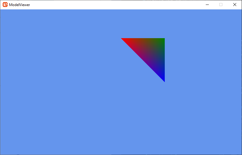
Finally, the line effect.VertexColorEnabled indicates we want to use the colors in the vertex data to set the color of the triangle. Since each corner has a different color, the pixels on the face of the triangle will be linearly interpolated by the distance to each corner, creating a gradient.
We’ll need to write a constructor that will call both the initialization methods, as well as accept the Game instance:
    /// <summary>
    /// Constructs a triangle instance
    /// </summary>
    /// <param name="game">The game that is creating the triangle</param>
    public Triangle(Game game)
    {
        this.game = game;
        InitializeVertices();
        InitializeEffect();
}And we’ll need to draw our triangle using our BasicEffect and GraphicDevice. Let’s put this code into a Draw() method:
    /// <summary>
    /// Draws the triangle
    /// </summary>
    public void Draw()
    {
        effect.CurrentTechnique.Passes[0].Apply();
        game.GraphicsDevice.DrawUserPrimitives<VertexPositionColor>(
            PrimitiveType.TriangleList,
            vertices,       // The vertex data
            0,              // The first vertex to use
            1               // The number of triangles to draw
        );
    }
An Effect can require multiple passes through the rendering pipeline, and can even contain multiple techniques. The line effect.CurrentTechnique.Passes[0].Apply() therefore sets up the graphics device for the first pass with the current technique (with our BasicEffect, it only has one pass). Then we trigger the rendering with game.GraphicsDevice.DrawUserPrimitives<VertexPositionColor>(...). We need to specify what kind of vertex data the graphics card should expect, hence the template <VertexPositionColor>. The first argument is the type of primitive to render. In our case, either PrimitiveType.TriangleList or PrimitiveType.TriangleStrip will work, as both use the first three vertices to define the first triangle, and we only have one. The second argument is an offset in our vertex data - we’re starting with the first, so its value is 0. The last argument is the number of primitives (in this case, triangles) to draw. We only have one defined, so its value is 1.
Now let’s use our Triangle in Game1. Add a field for the triangle to the Game1 class:
    // The triangle to draw
    Triangle triangle;
And construct it in our Game1.LoadContent(). We want to be sure the graphics device is set up before we construct our Triangle, so this is a good spot:
    // Create the triangle
    triangle = new Triangle(this);
And finally, let’s render it in our Game1.Draw() method:
    // Draw the triangle
    triangle.Draw();
If you run your code, you should now see the triangle rendered:
Let’s go one step farther, and make our triangle rotate around the center of the world. To do this, we’ll add an Update() method to our Triangle class, and modify the effect.World matrix:
    /// <summary>
    /// Rotates the triangle around the y-axis
    /// </summary>
    /// <param name="gameTime">The GameTime object</param>
    public void Update(GameTime gameTime)
    {
        float angle = (float)gameTime.TotalGameTime.TotalSeconds;
        effect.World = Matrix.CreateRotationY(angle);
    }
The gameTime.TotalGameTime.TotalSeconds represents the total time that has elapsed since the game started running. We pass this to the Matrix.CreateRotationY() to provide the angle (measured in radians) that the triangle should rotate.
Finally, we’ll need to add the Triangle.Update() call to our Game1.Update() method:
    // Update the triangle
    triangle.Update(gameTime);
Now when you run the program, your triangle rotates around the y-axis. But for 180 degrees of the rotation, it disappears! What is happening?
If we think back to the idea that the triangles in a 3D mesh are the surface of the object, it makes sense that we would only want to draw the outside faces (as the inside faces will always be obscured). This is exactly what the graphics device is doing - using a technique called backface culling to only draw triangles that are facing the camera (which eliminates around half the triangles in the scene).
But how do we know which face is the front-facing one? The graphics device uses winding order to determine this. Winding order refers to the order the vertices are presented to the hardware. We can change this value by changing the CullMode. By default, XNA uses CullCounterClockwiseFace; let’s try swapping that. Add these lines to your Triangle.Draw() method, before you invoke DrawUserPrimitives():
    // Change the backface culling mode
    RasterizerState rasterizerState = new RasterizerState();
    rasterizerState.CullMode = CullMode.CullClockwiseFace;
    game.GraphicsDevice.RasterizerState = rasterizerState;
Now its the other face of the triangle that does not appear! Try changing the CullMode.CullClockwiseFace to CullMode.None. Now both faces appear!
It is a good idea to cache the prior state before you make changes, and restore them when we’re done. I.e., we should refactor our Draw() method to:
    /// <summary>
    /// Draws the triangle
    /// </summary>
    public void Draw()
    {
        // Cache old rasterizer state
        RasterizerState oldState = game.GraphicsDevice.RasterizerState;

        // Disable backface culling
        RasterizerState rasterizerState = new RasterizerState();
        rasterizerState.CullMode = CullMode.None;
        game.GraphicsDevice.RasterizerState = rasterizerState;

        // Apply our effect
        effect.CurrentTechnique.Passes[0].Apply();

        // Draw the triangle
        game.GraphicsDevice.DrawUserPrimitives<VertexPositionColor>(
            PrimitiveType.TriangleList,
            vertices,       // The vertex data
            0,              // The first vertex to use
            1               // The number of triangles to draw
        );

        // Restore the prior rasterizer state
        game.GraphicsDevice.RasterizerState = oldState;
    }
Otherwise, our change to the rasterizer state could affect other things we are drawing.
While the point of a TriangleStrip is to optimize by reducing the number of vertices, in most cases it still will have repeats, and it is difficult to define a complex mesh out of a single strip. Thus, in addition to vertices, we can provide indices to specific vertices. The collection of indices contains nothing more than integers referencing vertices in the vertices collection. This means each unique vertex needs to be defined exactly once, and the indices take on the role of defining the triangles by giving the position of each successive vertex in the triangle list in the vertex array.
Let’s give this a try by defining a Quad class with both vertices and indices:
/// <summary>
/// A class representing a quad (a rectangle composed of two triangles)
/// </summary>
public class Quad
{
    /// <summary>
    /// The vertices of the quad
    /// </summary>
    VertexPositionTexture[] vertices;

    /// <summary>
    /// The vertex indices of the quad
    /// </summary>
    short[] indices;

    /// <summary>
    /// The effect to use rendering the triangle
    /// </summary>
    BasicEffect effect;

    /// <summary>
    /// The game this cube belongs to
    /// </summary>
    Game game;
}
You will note that instead of our vertex structure being a VertexPositionColor, this time we’re using VertexPositionTexture. Instead of giving each vertex a color, this time we’ll be giving it a texture coordinate, and having our effect apply a texture to the face of the quad.
Note also that we use the short data type for our index array. As a quad has only four vertices (one in each corner), we only need four vertices to define one. If our vertices start at index 0, that means we only need to represent indices 1-4, so a short is more than sufficient. With a larger vertex array, we might need to use a larger type of integer.
As with our triangle, we’ll initialize our vertices in a helper method, InitializeVertices:
    /// <summary>
    /// Initializes the vertices of our quad
    /// </summary>
    public void InitializeVertices() {
        vertices = new VertexPositionTexture[4];
        // Define vertex 0 (top left)
        vertices[0].Position = new Vector3(-1, 1, 0);
        vertices[0].TextureCoordinate = new Vector2(0, -1);
        // Define vertex 1 (top right)
        vertices[1].Position = new Vector3(1, 1, 0);
        vertices[1].TextureCoordinate = new Vector2(1, -1);
        // define vertex 2 (bottom right)
        vertices[2].Position = new Vector3(1, -1, 0);
        vertices[2].TextureCoordinate = new Vector2(1, 0);
        // define vertex 3 (bottom left)
        vertices[3].Position = new Vector3(-1, -1, 0);
        vertices[3].TextureCoordinate = new Vector2(0, 0);
    }
The quad is two by two, centered on the origin. The texture coordinates are expressed as floats that fall in the range [0 … 1]. The texture coordinate (0,0) is the upper-left hand corner of our texture, and (1, 1) is the lower-right corner.
Now let’s define our indices in their own helper method, InitializeIndices. Let’s assume we’re using a triangle list, so we’ll need to define all six vertices (with a triangle strip we could cut this to 4):
    /// <summary>
    /// Initialize the indices of our quad
    /// </summary>
    public void InitializeIndices() {
        indices = new short[6];

        // Define triangle 0
        indices[0] = 0;
        indices[1] = 1;
        indices[2] = 2;
        // define triangle 1
        indices[3] = 2;
        indices[4] = 3;
        indices[5] = 0;
}And we’ll need to set up our effect, which we’ll again do in a method named InitializeEffect():
    /// <summary>
    /// Initializes the basic effect used to draw the quad
    /// </summary>
    public void InitializeEffect()
    {
        effect = new BasicEffect(game.GraphicsDevice);
        effect.World = Matrix.Identity;
        effect.View = Matrix.CreateLookAt(
            new Vector3(0, 0, 4), // The camera position
            new Vector3(0, 0, 0), // The camera target,
            Vector3.Up            // The camera up vector
        );
        effect.Projection = Matrix.CreatePerspectiveFieldOfView(
            MathHelper.PiOver4,                         // The field-of-view
            game.GraphicsDevice.Viewport.AspectRatio,   // The aspect ratio
            0.1f, // The near plane distance
            100.0f // The far plane distance
        );
        effect.TextureEnabled = true;
        effect.Texture = game.Content.Load<Texture2D>("monogame-logo");
    }
This looks almost identical to our triangle example. The only difference is in the last two lines - instead of setting effect.VertexColorEnabled, we’re setting effect.TextureEnabled to true, and providing the monogame-logo.png texture to the effect.
Now let’s write our Draw() method:
    /// <summary>
    /// Draws the quad
    /// </summary>
    public void Draw()
    {
        effect.CurrentTechnique.Passes[0].Apply();
        game.GraphicsDevice.DrawUserIndexedPrimitives<VertexPositionTexture>(
            PrimitiveType.TriangleList,
            vertices,   // The vertex collection
            0,          // The starting index in the vertex array
            4,          // The number of indices in the shape
            indices,    // The index collection
            0,          // The starting index in the index array
            2           // The number of triangles to draw
        );
}To wrap up the Quad, we’ll need to add a constructor that takes a parameter of type Game and invokes our initialization:
    /// <summary>
    /// Constructs the Quad
    /// </summary>
    /// <param name="game">The Game the Quad belongs to</param>
    public Quad(Game game)
    {
        this.game = game;
        InitializeVertices();
        InitializeIndices();
        InitializeEffect();
} Now let’s use our Quad in Game1. Add a field for the quad to the Game1 class:
    // The quad to draw
    Quad quad;
And construct it in our Game1.LoadContent(). We want to be sure the graphics device is set up before we construct our Quad, so this is a good spot:
    // Create the quad
    quad = new Quad(this);
And finally, let’s render it in our Game1.Draw() method:
// Draw the quad
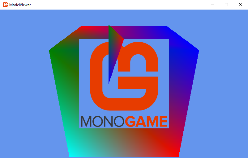
quad.Draw();If you run your code, you should now see the textured quad rendered:

Notice that even though our texture has a transparent background, the background is rendered in black. Alpha blending is managed by the GraphicsDevice.BlendState, so we’ll need to tweak it before we draw the quad:
game.GraphicsDevice.BlendState = BlendState.AlphaBlend;Notice the BlendState class is the same one we used with SpriteBatch - and it works the same way.
If you run the game now, the logo’s background will be properly transparent.
Just as with the RasterizerState, it is a good idea to restore the old BlendState. So our final Quad.Draw() method might look like:
/// <summary>
/// Draws the quad
/// </summary>
public void Draw()
{
    // Cache the old blend state
    BlendState oldBlendState = game.GraphicsDevice.BlendState;

    // Enable alpha blending
    game.GraphicsDevice.BlendState = BlendState.AlphaBlend;

    // Apply our effect
    effect.CurrentTechnique.Passes[0].Apply();

    // Render the quad
    game.GraphicsDevice.DrawUserIndexedPrimitives<VertexPositionTexture>(
        PrimitiveType.TriangleList,
        vertices,   // The vertex collection
        0,          // The starting index in the vertex array
        4,          // The number of indices in the shape
        indices,    // The index collection
        0,          // The starting index in the index array
        2           // The number of triangles to draw
    );

    // Restore the old blend state
    game.GraphicsDevice.BlendState = oldBlendState;
}
This Quad is very similar to the sprites we’ve worked with already - in fact, the SpriteBatch is an optimized way of drawing a lot of textured quads. It also configures the graphics device and has its own effect, the SpriteEffect. Because of this optimization, in most cases, you’ll want to use the SpriteBatch for textured quads. But it is good to understand how it is drawing 2D sprites using the 3D pipeline.
Speaking of… so far we’ve only drawn 2D shapes in a 3D world. Let’s move on to an actual 3D shape next.
We’ll continue our exploration of the rendering pipeline with another shape - a cube. And as before, we’ll introduce another concept - vertex and index buffers.
For our triangle and quad, we drew our shapes using GraphicsDevice.DrawUserPrimitives<T>() and GraphicsDevice.DrawUserIndexedPrimitives<T>(). Our vertices and indices were simply arrays we declared normally, that we passed to the graphics card using the aforementioned methods. As with most variables we deal with in C#, the memory used by the vertices and indices arrays was allocated from the computer’s RAM. When we invoked the methods, one of the tasks they do is stream the data to the GPU, so that it can be rendered.
This process can be significantly sped up if, instead of storing the vertex and index data in RAM, we store it in Video Ram (VRAM). VRAM is the memory that is a part of our graphics card. Not surprisingly, the GPU has direct access to VRAM and can stream data from it quite quickly - more quickly than it can from RAM. Especially if we are drawing the same shape using the same vertex and index data every frame.
So how do we get this data into the VRAM? We have to create a VertexBuffer and an IndexBuffer. Let’s create a Cube class with instances of these classes.
We’ll declare a Cube class much like our Triangle and Quad:
/// <summary>
/// A class for rendering a cube
/// </summary>
public class Cube
{
    /// <summary>
    /// The vertices of the cube
    /// </summary>
    VertexBuffer vertices;

    /// <summary>
    /// The vertex indices of the cube
    /// </summary>
    IndexBuffer indices;

    /// <summary>
    /// The effect to use rendering the cube
    /// </summary>
    BasicEffect effect;

    /// <summary>
    /// The game this cube belongs to
    /// </summary>
    Game game;
}
The only real difference at this point is the use of a VertexBuffer and IndexBuffer as fields.
We need to create the vertex data in much the same way we did with our other shapes - we start with a collection of vertices (we’ll use an array again, and give our vertices colors), but then we’ll copy that data into the VertexBuffer, which effectively copies it into VRAM (if space is available). Once again we’ll wrap this in an initialization method:
    /// <summary>
    /// Initialize the vertex buffer
    /// </summary>
    public void InitializeVertices()
    {
        var vertexData = new VertexPositionColor[] {
            new VertexPositionColor() { Position = new Vector3(-3,  3, -3), Color = Color.Blue },
            new VertexPositionColor() { Position = new Vector3( 3,  3, -3), Color = Color.Green },
            new VertexPositionColor() { Position = new Vector3(-3, -3, -3), Color = Color.Red },
            new VertexPositionColor() { Position = new Vector3( 3, -3, -3), Color = Color.Cyan },
            new VertexPositionColor() { Position = new Vector3(-3,  3,  3), Color = Color.Blue },
            new VertexPositionColor() { Position = new Vector3( 3,  3,  3), Color = Color.Red },
            new VertexPositionColor() { Position = new Vector3(-3, -3,  3), Color = Color.Green },
            new VertexPositionColor() { Position = new Vector3( 3, -3,  3), Color = Color.Cyan }
        };
        vertices = new VertexBuffer(
            game.GraphicsDevice,            // The graphics device to load the buffer on
            typeof(VertexPositionColor),    // The type of the vertex data
            8,                              // The count of the vertices
            BufferUsage.None                // How the buffer will be used
        );
        vertices.SetData<VertexPositionColor>(vertexData);
    }
We declare our vertexData as an instance variable, which means once this method returns, its memory will be reclaimed. The VertexBuffer constructor allocates the space needed for the data in VRAM, while the VertexBuffer.SetData() method what actually copies it into that location, managing the process for us.
If we were writing DirectX code in C++, we would need to:
If you are interested in seeing what the equivalent code in C++ looks like, visit www.directxtutorial.com. Our vertex and index data is adapted from the cube presented there.
The index buffer is initialized and the data copied in the same way:
    /// <summary>
    /// Initializes the index buffer
    /// </summary>
    public void InitializeIndices()
    {
        var indexData = new short[]
        {
            0, 1, 2, // Side 0
            2, 1, 3,
            4, 0, 6, // Side 1
            6, 0, 2,
            7, 5, 6, // Side 2
            6, 5, 4,
            3, 1, 7, // Side 3
            7, 1, 5,
            4, 5, 0, // Side 4
            0, 5, 1,
            3, 7, 2, // Side 5
            2, 7, 6
        };
        indices = new IndexBuffer(
            game.GraphicsDevice,            // The graphics device to use
            IndexElementSize.SixteenBits,   // The size of the index
            36,                             // The count of the indices
            BufferUsage.None                // How the buffer will be used
        );
        indices.SetData<short>(indexData);
}And our BasicEffect is configured identically to how we di so for our Triangle class:
    /// <summary>
    /// Initializes the BasicEffect to render our cube
    /// </summary>
    void InitializeEffect()
    {
        effect = new BasicEffect(game.GraphicsDevice);
        effect.World = Matrix.Identity;
        effect.View = Matrix.CreateLookAt(
            new Vector3(0, 0, 4), // The camera position
            new Vector3(0, 0, 0), // The camera target,
            Vector3.Up            // The camera up vector
        );
        effect.Projection = Matrix.CreatePerspectiveFieldOfView(
            MathHelper.PiOver4,                         // The field-of-view
            game.GraphicsDevice.Viewport.AspectRatio,   // The aspect ratio
            0.1f, // The near plane distance
            100.0f // The far plane distance
        );
        effect.VertexColorEnabled = true;
}Our cube.Draw() method will be a bit different though:
    /// <summary>
    /// Draws the Cube
    /// </summary>
    public void Draw()
    {
        // apply the effect
        effect.CurrentTechnique.Passes[0].Apply();
        // set the vertex buffer
        game.GraphicsDevice.SetVertexBuffer(vertices);
        // set the index buffer
        game.GraphicsDevice.Indices = indices;
        // Draw the triangles
        game.GraphicsDevice.DrawIndexedPrimitives(
            PrimitiveType.TriangleList, // Tye type to draw
            0,                          // The first vertex to use
            0,                          // The first index to use
            12                          // the number of triangles to draw
        );
    }
Before we can use GraphicsDevice.DrawIndexedPrimitives(), we need to tell the GraphicsDevice which VertexBuffer and IndexBuffer to use. The first is set with a method, the second through assignment. With both set, we can invoke GraphicsDevice.DrawIndexedPrimitives() and it will draw the contents of the buffers.
The Cube constructor is back in familiar territory:
    /// <summary>
    /// Constructs a cube instance
    /// </summary>
    /// <param name="game">The game that is creating the cube</param>
    public Cube(Game1 game)
    {
        this.game = game;
        InitializeVertices();
        InitializeIndices();
        InitializeEffect();
}To render our cube, we must go back to the Game1 class and add a reference to one:
    // The cube to draw
    Cube cube;
Construct it in the Game1.LoadContent() method:
    // Create the cube
    cube = new Cube(this);
And draw it in the Game1.Draw() method:
    // draw the cube
    cube.Draw();
If you run your code now, the cube is so big that the front face takes up the whole screen!
We could scale our cube down with a world transform - but rather than doing that, let’s look at it from farther away by changing the view transform. Let’s add an Update() method to our Cube class:
    /// <summary>
    /// Updates the Cube
    /// </summary>
    /// <param name="gameTime"></param>
    public void Update(GameTime gameTime)
    {
        // Look at the cube from farther away
        effect.View = Matrix.CreateLookAt(
            new Vector3(0, 5, -10),
            Vector3.Zero,
            Vector3.Up
        );
    }
And invoke this method in the Game1.Update() method:
    // update the cube
    cube.Update(gameTime);
Now if you run the program, you should see the cube, and be able to see that its edges are distorted to simulate depth:
Let’s set our viewpoint rotating around the cube by refactoring our Cube.Update() method:
    /// <summary>
    /// Updates the Cube
    /// </summary>
    /// <param name="gameTime"></param>
    public void Update(GameTime gameTime)
    {
        float angle = (float)gameTime.TotalGameTime.TotalSeconds;
        // Look at the cube from farther away while spinning around it
        effect.View = Matrix.CreateRotationY(angle) * Matrix.CreateLookAt(
            new Vector3(0, 5, -10),
            Vector3.Zero,
            Vector3.Up
        );
    }
Now our cube appears to be spinning! But actually, it is our vantage point that is circling the cube, unlike the triangle, which is actually spinning in place. The final effect is the same, but one spin is applied to the world transform, and the other to the view transform. We’ll speak about both in more detail later.
This wraps up our discussion of the basics of 3D rendering. As you might expect, this is just the basic foundations. From here we’ll explore using models, creating lighting effect, animations, and more. But all of these will depend on understanding and using these basic elements, so get comfortable with them!