It Starts with Triangles
You probably remember from our discussions of matrix math that we can create matrices to represent arbitrary transformations. Moreover, we can transform a vector by multiplying it by one of these transformation matrices. This is the mathematical foundations of hardware-accelerated 3D rendering. In fact, the GPU is nothing more than a processor optimized for performing matrix and vector operations.
We model our three-dimensional worlds with triangles. Lots and lots of triangles. Why triangles? Remember that three points define a plane. Three points also can define a triangle. So we know that the three endpoints of a triangle will always be coplanar. If we used more than three points, there is a possibility that we might screw up and have one out-of-plane, which would break the process. So 3D rendering is almost entirely based on rendering triangles (you can also render lines and points with OpenGL and DirectX, but XNA only supports triangles and lines).
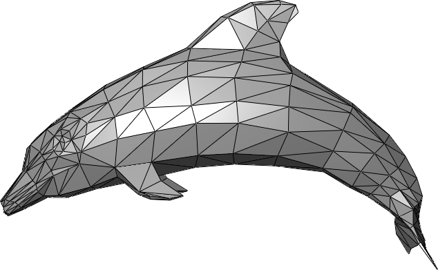
Complex objects are therefore composed of multiple triangles, which typically share sides and create a closed shape with a distinct inside and outside. We call these triangle meshes, and they effectively create a hollow shell in the shape of the object to be rendered:
Vertices
Rather than creating structures for storing triangles, we store the endpoints of the triangles as vertices. These vertices are a data structure that (at a minimum) defines the coordinate of the triangle endpoint in three dimensions (A Vector3 in XNA). Vertices can contain additional data needed to render the mesh, including color, texture coordinates, and additional vectors like the surface normal (a Vector3 pointing out from the surface).
Let’s create a class to represent our cube, and give it an array of vertices that have both a position and a color:
/// <summary>
/// A class for rendering a single triangle
/// </summary>
public class Triangle
{
    /// <summary>
    /// The vertices of the triangle
    /// </summary>
    VertexPositionColor[] vertices;

}
Note the VertexPositionColor is defined in the Microsoft.Xna.Framework.Graphics namespace.
Triangles
Triangles are then defined by the order the vertices are presented to the graphics card, defined by a graphics primitive type. There are four supported by XNA, and appear in the PrimitiveType enumeration. These are LineList, LineStrip, TriangleList, and TriangleStrip. The first two vertices in a LineList define the two endpoints of a line, the second two, a second line. In contrast, with a LineStrip each successive line connects to the previous one, sharing a vertex. Thus vertices 0 and 1 define the first line, vertices 1 and 2 define the second, vertices 2 and 3 the third, and so on…
The TriangleList and TriangleStrip work the same way. In a TriangleList each three vertices define a single triangle. Hence vertices 0, 1, and 2 define the first triangle, and vertices 3, 4, and 5, the second, and so on. With the TriangleStrip, vertices 0, 1, and 2 define the first triangle; vertices 1, 2, and 3 define the second, vertices 2, 3, and 4 the third, and so on…
Our Triangle will only be using vertices 0, 1, and 2, so either approach will be identical. Let’s go ahead and define those vertices in a helper method:
    /// <summary>
    /// Initializes the vertices of the triangle
    /// </summary>
    void InitializeVertices()
    {
        vertices = new VertexPositionColor[3];
        // vertex 0
        vertices[0].Position = new Vector3(0, 1, 0);
        vertices[0].Color = Color.Red;
        // vertex 1
        vertices[1].Position = new Vector3(1, 1, 0);
        vertices[1].Color = Color.Green;
        // vertex 2
        vertices[2].Position = new Vector3(1, 0, 0);
        vertices[2].Color = Color.Blue;
    }
The Effect
One of the major innovations of hardware graphics has been the introduction of programmable shaders. A shader is simply a program that runs on a GPU, and performs some steps of the graphics pipeline. At the time XNA was created, there were three points in the graphics pipeline where programmable shaders could be inserted: the vertex shader, the geometry shader, and the pixel shader (additional shader points have been added to graphics cards since). These shaders are written in a language specific to the GPU and graphics library (DirectX or OpenGL). In XNA, this language is HLSL.
XNA seeks to simplify the details of setting up shaders by abstracting the heavy lifting into the Effect Class. An Effect handles configuring the graphics device to produce a specific effect through a combination of shaders and hardware settings. We can create custom classes derived from the Effect class, or use one of those already defined in XNA:
With our triangle, we’ll use the BasicEffect, which provides a basic rendering pipeline. Let’s add a field for one to our Triangle class:
    /// <summary>
    /// The effect to use rendering the triangle
    /// </summary>
    BasicEffect effect;
The effect also needs a reference to the GraphicsDevice held by our Game instance; so let’s also add a Game field:
    /// <summary>
    /// The game this triangle belongs to
    /// </summary>
    Game game;
You’ll also need to add the Microsoft.Xna.Framework namespace to make Game available.
Now let’s initialize our effects settings in a second helper method, InitializeEffect():
    /// <summary>
    /// Initializes the BasicEffect to render our triangle
    /// </summary>
    void InitializeEffect()
    {
        effect = new BasicEffect(game.GraphicsDevice);
        effect.World = Matrix.Identity;
        effect.View = Matrix.CreateLookAt(
            new Vector3(0, 0, 4), // The camera position
            new Vector3(0, 0, 0), // The camera target,
            Vector3.Up            // The camera up vector
        );
        effect.Projection = Matrix.CreatePerspectiveFieldOfView(
            MathHelper.PiOver4,                         // The field-of-view
            game.GraphicsDevice.Viewport.AspectRatio,   // The aspect ratio
            0.1f, // The near plane distance
            100.0f // The far plane distance
        );
        effect.VertexColorEnabled = true;
    }
There’s a lot going on here, so lets’ break it down.
The World Matrix
The line effect.World = Matrix.Identity creates the world matrix. This matrix embodies a transformation that transforms our vertices from model space to game space. Consider our triangle - it has three endpoints (0, 1, 0), (1, 1, 0), and (1, 0, 0). As it is defined, it has one endpoint above the origin, one to the right, and the third is above and to the right - in line with the others. This is its model space. We might want it to appear somewhere else in our game world - say at (100, 100, 0). We call our game world world space, and a matrix that would embody the transformation needed to move our triangle from its model space coordinates to its world space coordinates is the world matrix. We’re using Matrix.Identity here, which won’t change those coordinates at all.
Instead of thinking of triangles, think of crates. We probably would use the same crate multiple times throughout our game. The crate would have been drawn in a modeling program, and probably had its origin at a corner or bottom corner (model space). When we put it into the level, we would translate and rotate it to get it in just the right spot (world space). We might put a second copy in a different location, with its own translation. Hence, the two instances would have the same model coordinates, but different transformations to place them in the world, embodied in different world matrices.
The View Matrix
The line effect.View = Matrix.CreateLookAt(..) creates the view matrix. This is the transform that shifts us from world space into view space. View space is relative to the position of the observer - the eye (or camera) is at the origin (0, 0, 0), and they are looking along the z-axis. Since the observer exists somewhere in the game world, the view transformation shifts the coordinate system so that that position becomes the origin, and everything in the world moves along with it.
Matrix.CreateLookAt() is a method for creating a matrix to embody this transformation, and allows us to specify where the observer is looking from, and to. The first argument is the position of the observer - where the observer’s eye would be in the world. The second argument is a vector in the direction the observer is looking. The third helps orient the observer by defining which direction is up. Normally this would be the up vector (0, 1, 0), but if the observer was a plane that was executing a barrel roll, it would be the down vector (0, -1, 0) halfway through the roll, and every value between as the plane rolled.
The Projection Matrix
The line effect.Projection = Matrix.CreatePerspectiveFieldOfView(...) creates the projection matrix. This is the matrix that transforms our 3D scene into a 2D one. It does this by setting z-values to 0 while (possibly) tweaking x- and y-values to create the illusion of perspective. There are two commonly used projections in video games: orthographic, which simply removes the z-values, flattening the scene; and perspective, which stretches distant objects an squishes near ones, creating the illusion of depth.
Matrix.CreatePerspectiveFieldOfView() creates a perspective matrix that accounts for the field of view of the observer. The first argument is an angle measuring how wide the field of view should be, measured in radians. Humans have approximately a 120 degree field-of-view, but most of this is peripheral vision, so we typically use smaller numbers. This can also be tweaked to provide the illusion of using a telescope or wide lens. The second argument is the aspect ratio - this should match the aspect ratio of the screen, or the result will seem distorted. For this reason we draw its value directly from the GraphicsDevice. The last two values are floats indicating the far and near planes. The near plane is how close objects can be to the observer before they won’t be rendered, and the far plan is how far away they can be.
Matrix.CreateOrthographic() creates an orthographic matrix. As there is no distortion, its arguments simply describe a cube, with the near plane and far plane composing the nearest and farthest sides. The near face is centered on the observer, and only the vertices within the cube are rendered.
Vertex Color
Finally, the line effect.VertexColorEnabled indicates we want to use the colors in the vertex data to set the color of the triangle. Since each corner has a different color, the pixels on the face of the triangle will be linearly interpolated by the distance to each corner, creating a gradient.
Constructing the Triangle
We’ll need to write a constructor that will call both the initialization methods, as well as accept the Game instance:
    /// <summary>
    /// Constructs a triangle instance
    /// </summary>
    /// <param name="game">The game that is creating the triangle</param>
    public Triangle(Game game)
    {
        this.game = game;
        InitializeVertices();
        InitializeEffect();
    }
Drawing the Triangle
And we’ll need to draw our triangle using our BasicEffect and GraphicDevice. Let’s put this code into a Draw() method:
    /// <summary>
    /// Draws the triangle
    /// </summary>
    public void Draw()
    {
        effect.CurrentTechnique.Passes[0].Apply();
        game.GraphicsDevice.DrawUserPrimitives<VertexPositionColor>(
            PrimitiveType.TriangleList,
            vertices,       // The vertex data
            0,              // The first vertex to use
            1               // The number of triangles to draw
        );
    }
An Effect can require multiple passes through the rendering pipeline, and can even contain multiple techniques. The line effect.CurrentTechnique.Passes[0].Apply() therefore sets up the graphics device for the first pass with the current technique (with our BasicEffect, it only has one pass). Then we trigger the rendering with game.GraphicsDevice.DrawUserPrimitives<VertexPositionColor>(...). We need to specify what kind of vertex data the graphics card should expect, hence the template <VertexPositionColor>. The first argument is the type of primitive to render. In our case, either PrimitiveType.TriangleList or PrimitiveType.TriangleStrip will work, as both use the first three vertices to define the first triangle, and we only have one. The second argument is an offset in our vertex data - we’re starting with the first, so its value is 0. The last argument is the number of primitives (in this case, triangles) to draw. We only have one defined, so its value is 1.
Adding the Triangle to Game1
Now let’s use our Triangle in Game1. Add a field for the triangle to the Game1 class:
    // The triangle to draw
    Triangle triangle;
And construct it in our Game1.LoadContent(). We want to be sure the graphics device is set up before we construct our Triangle, so this is a good spot:
    // Create the triangle
    triangle = new Triangle(this);
And finally, let’s render it in our Game1.Draw() method:
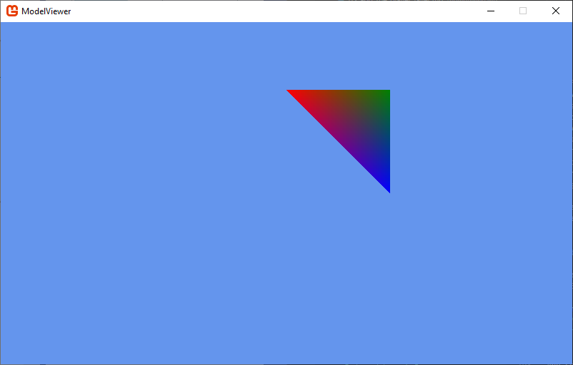
    // Draw the triangle
    triangle.Draw();
If you run your code, you should now see the triangle rendered:
Rotating the Triangle
Let’s go one step farther, and make our triangle rotate around the center of the world. To do this, we’ll add an Update() method to our Triangle class, and modify the effect.World matrix:
    /// <summary>
    /// Rotates the triangle around the y-axis
    /// </summary>
    /// <param name="gameTime">The GameTime object</param>
    public void Update(GameTime gameTime)
    {
        float angle = (float)gameTime.TotalGameTime.TotalSeconds;
        effect.World = Matrix.CreateRotationY(angle);
    }
The gameTime.TotalGameTime.TotalSeconds represents the total time that has elapsed since the game started running. We pass this to the Matrix.CreateRotationY() to provide the angle (measured in radians) that the triangle should rotate.
Finally, we’ll need to add the Triangle.Update() call to our Game1.Update() method:
    // Update the triangle
    triangle.Update(gameTime);
Now when you run the program, your triangle rotates around the y-axis. But for 180 degrees of the rotation, it disappears! What is happening?
Backface Culling
If we think back to the idea that the triangles in a 3D mesh are the surface of the object, it makes sense that we would only want to draw the outside faces (as the inside faces will always be obscured). This is exactly what the graphics device is doing - using a technique called backface culling to only draw triangles that are facing the camera (which eliminates around half the triangles in the scene).
But how do we know which face is the front-facing one? The graphics device uses winding order to determine this. Winding order refers to the order the vertices are presented to the hardware. We can change this value by changing the CullMode. By default, XNA uses CullCounterClockwiseFace; let’s try swapping that. Add these lines to your Triangle.Draw() method, before you invoke DrawUserPrimitives():
    // Change the backface culling mode
    RasterizerState rasterizerState = new RasterizerState();
    rasterizerState.CullMode = CullMode.CullClockwiseFace;
    game.GraphicsDevice.RasterizerState = rasterizerState;
Now its the other face of the triangle that does not appear! Try changing the CullMode.CullClockwiseFace to CullMode.None. Now both faces appear!
It is a good idea to cache the prior state before you make changes, and restore them when we’re done. I.e., we should refactor our Draw() method to:
    /// <summary>
    /// Draws the triangle
    /// </summary>
    public void Draw()
    {
        // Cache old rasterizer state
        RasterizerState oldState = game.GraphicsDevice.RasterizerState;

        // Disable backface culling
        RasterizerState rasterizerState = new RasterizerState();
        rasterizerState.CullMode = CullMode.None;
        game.GraphicsDevice.RasterizerState = rasterizerState;

        // Apply our effect
        effect.CurrentTechnique.Passes[0].Apply();

        // Draw the triangle
        game.GraphicsDevice.DrawUserPrimitives<VertexPositionColor>(
            PrimitiveType.TriangleList,
            vertices,       // The vertex data
            0,              // The first vertex to use
            1               // The number of triangles to draw
        );

        // Restore the prior rasterizer state
        game.GraphicsDevice.RasterizerState = oldState;
    }
Otherwise, our change to the rasterizer state could affect other things we are drawing.