Heightmap Terrain
Keep your feet on the ground!
Keep your feet on the ground!
Now that we understand how 3D worlds are built from triangle meshes, and how we can use cameras to explore those worlds, let’s start putting those ideas to work. In this section, we’ll focus on creating terrain from a heightmap - a grayscale bitmap representing the changing elevation of the ground.
Like our earlier examples, we’ll start from a starter project with our assets pre-loaded. In addition, we’ll include the ICamera interface and the FPSCamera we created in the lesson on Lights and Cameras. It is also preloaded with public-domain content assets, including a heightmap from Wikimedia and a grass texture from Para on OpenGameArt’s Synthetic Grass Texture Pack.
You can find the starter project here: https://github.com/ksu-cis/heightmap-terrain-starter
You might be wondering just what a heightmap is. If you’ve ever used a topographic map, you’ve seen a similar idea. Contour maps include contour lines_, lines that trace when the ground reaches a certain altitude. Inside the line is higher than that altitude, and outside of the line is lower (or visa-versa). The contours themselves are typically marked with the altitude they represent.
A heightmap is similar, but instead of using lines, each pixel in the map represents a square section of land, and the color value at that point indicates the average altitude of that square. Since there is only one value to represent, heightmaps are typically created in grayscale. And, to optimize space, they may also be saved in a monochrome format (where each pixel is stored as a single 8-bit value, instead of the 32-bits typical for storing RGB values).

You can obtain heightmaps in a number of ways. You can draw a heightmap with any raster graphics program, though it takes a lot of skill and patience to make one that mimics natural terrain. You can also get real-world heightmaps directly from organizations like the USGS or NASA’s Viewfinder Project. Or you can generate one using Perlin Noise and algorithms that mimic the results of plate tectonics. There also exist many height-map generation programs, both open-source and commercial.
Along with the height map, you also need to know the sampling resolution (how large each terrain square should be), and the scale that should be applied to the heights (as the pixel values of the heightmap will be in values between 0 and 255).
Now, let’s turn our attention to creating a Terrain class that will use a heightmap.
We’ll start with the class definition:
/// <summary>
/// A class representing terrain
/// </summary>
public class Terrain
{
    // The game this Terrain belongs to
    Game game;
}
As with most of our classes, we’ll keep a reference to the Game object to access the shared ContentManager and GraphicsDevice.
We could store our heightmap directly, but all we really need out of it are the height values, and these need to be scaled. So instead, we’ll store the result of that computation in a 2D array of floats:
    // The height data
    float[,] heights;
It’s also convenient to keep track of the width and height of our terrain (in grid cells), and the total number of triangles in the terrain’s mesh:
    // The number of cells in the x-axis
    int width;

    // The number of cells in the z-axis
    int height;

    // The number of triangles in the mesh
    int triangles;
To render the heightmap, we need a VertexBuffer and IndexBuffer to represent our triangle mesh, and a BasicEffect to render it, and a Texture2D to apply to it:
    // The terrain mesh vertices
    VertexBuffer vertices;

    // The terrain mesh indices
    IndexBuffer indices;

    // The effect used to render the terrain
    BasicEffect effect;

    // The texture to apply to the terrain surface
Texture2D texture;We’ll write a helper method, LoadHeights(), to convert our heightmap from a Texture2D into our 2D array of floats. As you might expect from our earlier discussion, we’ll also need to know the scaling factor for determining the height. We’ll take these as parameters to our method:
    /// <summary>
    /// Converts the supplied Texture2D into height data
    /// </summary>
    /// <param name="heightmap">The heightmap texture</param>
    /// <param name="scale">The difference between the highest and lowest elevation</param>
    private void LoadHeights(Texture2D heightmap, float scale)
    {
    }
An easy way to define the scale is to use the difference between the lowest and highest elevations, in the units of the game world. If we treat the color of the pixel as a value between 0 and 1, we can just multiply the scale by the color. Unfortunately, our color channels in a Texture2D are actually represented as a byte with value between 0 and 255. But we can transform that into our desired range by dividing that value by 256. Instead of doing that division operation in a loop (causing N*M divisions where N is the width of the heightmap and M is the width), we can pre-divide the scale, and get the same effect with a single division operation:
    // Convert the scale factor to work with our color
   scale /= 256;
We’ll also set the width and height properties to match the dimensions of our heightmap:
    // The number of grid cells in the x-direction
    width = heightmap.Width;

    // The number of grid cells in the z-direction
    height = heightmap.Height;
Which will also be the dimensions of our heights array:
heights = new float[width, height]; Now, we need to get the color data from our heightmap. We can extract that with the Texture2D.GetData() method. This returns the data as a one-dimensional array of Color structures.
    // Get the color data from the heightmap
    Color[] heightmapColors = new Color[width * height];
    heightmap.GetData<Color>(heightmapColors);
We can then iterate through our heights array, setting each entry to the color value extracted from the heightmap scaled by our scaling factor:
    // Set the heights
    for (int y = 0; y < height; y++)
    {
        for (int x = 0; x < width; x++)
        {
            heights[x, y] = heightmapColors[x + y * width].R * scale;
        }
    }
Remember that we can convert from two-dimensional array indices to a one-dimensional index with the equation index = x + y * width].
After setting the heights, we’ve finished with this method. Next we’ll tackle creating our vertices
We’ll create our vertices in an InitializeVertices() helper method:
    /// <summary>
    /// Creates the terrain vertex buffer
    /// </summary>
    private void InitializeVertices()
    {
    }
We’ll start by creating an array to hold our vertex data. We’ll use the VertexPositionNormalTexture structure as the type of our vertices. The size of this array will be the same size as the heightmap data:
VertexPositionNormalTexture[] terrainVertices = new VertexPositionNormalTexture[width * height]; We’ll also create an index variable to simplify the transition between our 2D heights array and our 1D vertex array:
int i = 0;Now we can iterate through the vertex data, setting the Position, Normal, and Texture properties of each vertex:
    for(int z = 0; z < height; z++)
    {
        for(int x = 0; x < width; x++)
        {
            terrainVertices[i].Position = new Vector3(x, heights[x, z], -z);
            terrainVertices[i].Normal = Vector3.Up;
            terrainVertices[i].TextureCoordinate = new Vector2((float)x / 50f, (float)z / 50f);
            i++;
        }
    }
A couple of things to be aware of:
Armed with our vertex data, we can create and populate our VertexBuffer:
    vertices = new VertexBuffer(game.GraphicsDevice, typeof(VertexPositionNormalTexture), terrainVertices.Length, BufferUsage.None);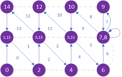
vertices.SetData<VertexPositionNormalTexture>(terrainVertices);Before we dive into code, let’s think about how we want to lay out our triangle mesh. We could use either a triangle list, or a triangle strip. With a triangle list, we need to have an index for each of the corners of each triangle. Since we have two triangles per grid cell, the total number of indices would be indexCount = 3 * width * height. Conversely, with a triangle strip, we only need one index for each triangle after the first, which needs three. So its size would be indexCount = width * height + 2. This is nearly a third of the size! So naturally, we’d like to use a triangle list. This is pretty straightforward for a single row:
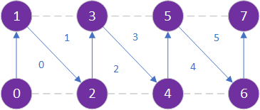
The diagram above shows what a row defined as a triangle strip looks like. Each vertex (the purple circle) is labeled by the order it appears in the indices. The blue arrows denote the triangle edges defined by successive vertices. The gray dashed lines denote the side of the triangle inferred from the order of the vertices. And each triangle is numbered in blue by the order it is defined.
But what about the next row? You might be tempted to start on the left again, but doing so will result in a triangle that stretches across the breadth of the terrain - which will look terrible!
This triangle is outlined in the above diagram by the ochre lines. Note that in the game they won’t be curved - the triangle will just slice through the terrain.
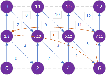
Or, we can try zig-zagging, by going right-to-left with the second row.
Notice that doing so creates a triangle that stretches along the end of the terrain. This probably wouldn’t be a problem as we probably would obscure the edge of our terrain in the game anyway. But also notice that the diagonals of each terrain row slant the opposite ways. This does cause a problem for us, which we’ll understand in a bit.
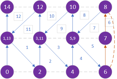
Instead, we’ll create two extra triangles between each row.
Notice that for the two extra triangles created by this pattern, 6 and 7, two of their vertices are the same. This means they are actually lines! And they will be rendered as part of the edge of triangles 5 and 8. Moreover, all our diagonals are slanting the same direction.
Let’s use this pattern as we declare our indices in the helper method InitializeIndices():
    /// <summary>
    /// Creates the index buffer
    /// </summary>
    private void InitializeIndices()
    {
    }
We need to know how many indices are needed to draw our triangles, and use this value to initialize our index array:
    // The number of triangles in the triangle strip
    triangles = (width) * 2 * (height - 1);

    int[] terrainIndices = new int[triangles];
We’ll also need a couple of index variables:
    int i = 0;
    int z = 0;
Now as we iterate over the terrain, we’ll need to reverse the direction each row. So we’ll use two inner loops, one for the row running left, and one for the row running right. Since we don’t know which will be our last row, we’ll use the same invariant for both (z < height - 1):
    while(z < height - 1)
    {
        for(int x = 0; x < width; x++)
        {
            terrainIndices[i++] = x + z * width;
            terrainIndices[i++] = x + (z + 1) * width;
        }
        z++;
        if(z < height - 1)
        {
            for(int x = width - 1; x >= 0; x--)
            {
                terrainIndices[i++] = x + (z + 1) * width;
                terrainIndices[i++] = x + z * width;
            }
        }
        z++;
    }
Another slight optimization we can perform is determining if we can get away with using 16-bit indices, or if we need 32-bit indices. This is determined by size of our vertex buffer - we need to be able to hold its largest index:
IndexElementSize elementSize = (width * height > short.MaxValue) ? IndexElementSize.ThirtyTwoBits : IndexElementSize.SixteenBits;Finally, we can create and populate our index buffer:
    indices = new IndexBuffer(game.GraphicsDevice, elementSize, terrainIndices.Length, BufferUsage.None);
indices.SetData<int>(terrainIndices);We’ll also initialize our BasicEffect, turning on texture rendering and setting our texture. We’ll also set our world matrix here.
    /// <summary>
    /// Initialize the effect used to render the terrain
    /// </summary>
    /// <param name="world">The world matrix</param>
    private void InitializeEffect(Matrix world)
    {
        effect = new BasicEffect(game.GraphicsDevice);
        effect.World = world;
        effect.Texture = texture;
        effect.TextureEnabled = true;
    }
We can skip setting the view and projection matrices, as these will come from our camera supplied to the Draw() method.
The constructor will invoke each of the initialization helper methods we just wrote:
    /// <summary>
    /// Constructs a new Terrain
    /// </summary>
    /// <param name="game">The game this Terrain belongs to</param>
    /// <param name="heightmap">The heightmap used to set heights</param>
    /// <param name="heightRange">The difference between the lowest and highest elevation in the terrain</param>
    /// <param name="world">The terrain's position and orientation in the world</param>
    public Terrain(Game game, Texture2D heightmap, float heightRange, Matrix world)
    {
        this.game = game;
        texture = game.Content.Load<Texture2D>("ground_grass_gen_08");
        LoadHeights(heightmap, heightRange);
        InitializeVertices();
        InitializeIndices();
        InitializeEffect(world);
    }
It also loads the default grass texture.
Finally, we can turn our attention to drawing the terrain, which is done just like our prior examples:
    /// <summary>
    /// Draws the terrain
    /// </summary>
    /// <param name="camera">The camera to use</param>
    public void Draw(ICamera camera)
    {
        effect.View = camera.View;
        effect.Projection = camera.Projection;
        effect.CurrentTechnique.Passes[0].Apply();
        game.GraphicsDevice.SetVertexBuffer(vertices);
        game.GraphicsDevice.Indices = indices;
        game.GraphicsDevice.DrawIndexedPrimitives(PrimitiveType.TriangleStrip, 0, 0, triangles);
    }
Next we’ll make some changes in our Game class to use our terrain.
Let’s see our terrain in action. First we’ll need to make some changes in our ExampleGame class. We’ll add a Terrain field:
    // The terrain
    Terrain terrain;
In our ExampleGame.LoadContent(), we’ll load the heightmap and construct our terrain:
    // Build the terrain
    Texture2D heightmap = Content.Load<Texture2D>("heightmap");
    terrain = new Terrain(this, heightmap, 10f, Matrix.Identity);
And in our ExampleGame.Draw() we’ll render it with the existing camera:
    // Draw the terrain
    terrain.Draw(camera);
Now if you run the game, you should see your terrain, and even be able to move around it using the camera controls (WASD + Mouse).
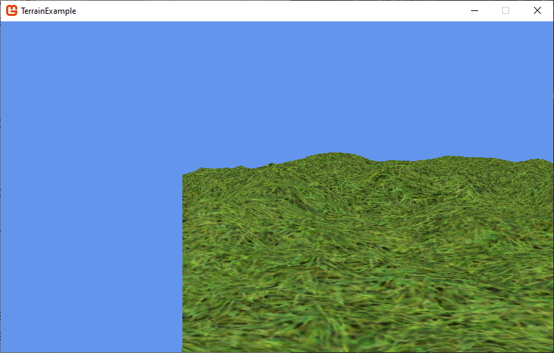
You’ll probably notice that your camera does not change position as you move over the terrain - in fact, in some parts of the map you can actually end up looking up from underneath!
Clearly we need to do a bit more work. We need a way to tell the camera what its Y-value should be, based on what part of the terrain it is over.
Rather than linking our camera directly to our terrain implementation, let’s define an interface that could be used for any surface the player might be walking on. For lack of a better name, I’m calling this interface IHeightMap:
    /// <summary>
    /// An interface providing methods for determining the
    /// height at a point in a height map
    /// </summary>
    public interface IHeightMap
    {
        /// <summary>
        /// Gets the height of the map at the specified position
        /// </summary>
        /// <param name="x">The x coordinate in the world</param>
        /// <param name="z">The z coordinate in the world</param>
        /// <returns>The height at the specified position</returns>
        float GetHeightAt(float x, float z);
    }
The interface defines a single method, GetHeightAt(). Note that we take the X and Z coordinate - these are world coordinates in the game. The return value is the Y world coordinate corresponding to the elevation of the terrain at x and z.
We can then use this interface within our FPSCamera class to change its height based on its X and Z. We’ll start by adding a property of type ICamera:
    /// <summary>
    /// Gets or sets the heightmap this camera is interacting with
    /// </summary>
    public IHeightMap HeightMap { get; set; }
And we’ll modify our FPSCamera.Update() to use the HeightMap’s height at the camera position, added to the camerea’s HeightOffset to determine the camera’s actual Y position:
    // Adjust camera height to heightmap
    if(HeightMap != null)
    {
        position.Y = HeightMap.GetHeightAt(position.X, position.Z) + HeightOffset;
    }
This should be done before we set the updated View matrix.
Notice that we wrap this in a null check. If there is no heightmap, we want to keep our default behavior.
Since the HeightMap is a property of the FPSCamera, we’ll need to set it to our terrain in the ExampleGame.LoadContent() method after both the camera and terrain have been created:
camera.HeightMap = Terrain;Now we need to implement the IHeightMap interface in our Terrain class. Add it to the class definition:
public class Terrain : IHeightMap {
    ...
}
And add the method it calls for:
    /// <summary>
    /// Gets the height of the terrain at
    /// the supplied world coordinates
    /// </summary>
    /// <param name="x">The x world coordinate</param>
    /// <param name="z">The z world coordinate</param>
    /// <returns></returns>
    public float GetHeightAt(float x, float z)
    {}
Now, let’s talk through the process of finding the height. As our comments suggest, we’re using world coordinates, not model coordinates. As long as the world matrix remains the identity matrix, these are the same. But as soon as that changes, the world coordinates no longer line up. So the first thing we need to do is transform them from world coordinates to model coordinates.
Since multiplying a vector in model coordinates by the world matrix transforms them into world coordinates, the inverse should be true. Specifically, multiplying world coordinates by the inverse of the world matrix should transform them into model coordinates.
The Matrix.Invert() method can create this inverse matrix:
Matrix inverseWorld = Matrix.Invert(effect.World);We’ll also need the world coordinates as a Vector3 to transform:
Vector3 worldCoordinates = new Vector3(x, 0, z);Here we don’t care about the y value, so we’ll set it to 0.
Then we can apply the transformation with Vector3.Transform():
Vector3 modelCoordinates = Vector3.Transform(worldCoordinates, inverseWorld);At this point, modelCoordinates.X and modelCoordinates.Z correspond to the x and -y indices of our heights array, respectively. The y coordinate needs to be inverted, because our terrain was defined along the negative z-axis (as the positive z-axis is towards the screen). Let’s save them in float variables so we don’t have to remember to invert the z as our y coordinate:
    float tx = modelCoordinates.X;
    float ty = -modelCoordinates.Z;
These should correspond to the x and y indices in the heights array, but it is also possible that they are out-of-bounds. It’s a good idea to check:
if (tx < 0 || ty < 0 || tx >= width || ty >= height) return 0;If we’re out-of-bounds, we’ll just return a height of 0. Otherwise, we’ll return the value in our heights array:
return heights[(int)tx, (int)ty];Now try running the game and exploring your terrain. The camera should now move vertically according to the elevation!
While you can now walk over your terrain, you probably notice that the camera seems really jittery. Why isn’t it smooth?
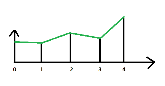
Think about how we render our terrain. The diagram below shows the terrain in one dimension. At each integral step, we have a height value. The terrain (represented by green lines) is interpolated between these heights.
Now think about what our function transforming world coordinates to heights is doing. It casts tx to an int to throw away the fractional part of the coordinate in order to get an array index. Thus, it is a step-like function, as indicated by the red lines in the diagram below:
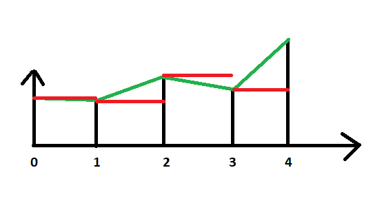
No wonder our movement is jerky!
Instead, we need to interpolate the height between the two coordinates, so we match up with the visual representation.
We could use a method like MathHelper.Lerp to interpolate between two height values:
    var height1 = height[(int)x]
    var height2 = height[(int)x + 1]
    var fraction = x - (int)x;
    MathHelper.Lerp(fraction, height1, height2);
What does linear interpolation actually do? Mathematically it’s quite simple:
height1)height2 - height1)x - floor(x))If we were to write our own linear interpolation implemenation, it might look like:
public float Lerp(float fraction, float value1, float value2)
{
    return value1 + fraction * (value2 - value1);
}
However, we aren’t working with just one dimension, we need to consider two. In other words, we need to use bilinear interpolation. But XNA does not define a method for this, so we’ll have to do it ourselves.
Bilinear interpolation is the extension of linear interpolation into two dimensions. Instead of interpolating a point on a line (as is the case with linear interpolation), in bilinear interpolation we are interpolating a point on a plane. But with our terrain, we have two planes per grid cell:
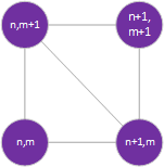
In this diagram, n and m are coordinates in our heights array, corresponding to the vertex making up the grid cell. So if our (x, y) point is in this grid cell, n < x < n+1 and m < y < m+1.
Remember, a triangle defines a plane, and we used two triangles to define each grid cell in our terrain. So we need to know which triangle our point falls on.
This is why we wanted our diagonals to both face the same way, and also why we wanted them facing the way they do. If the fractional distance along either the x or y axis is greater than halfway (0.5 in our model coordinates), then we are on the upper-right triangle. The inverse is also true; if both coordinates are less than halfway, we’re in the lower left triangle. Any coordinate falling on line between the two triangles is shared by both.
Let’s return to our Terrain.GetHeightAt() method, and start refactoring it. First, we’ll want to change our out-of-bounds test to be slightly more exclusive, as we’ll be getting both the height values at both the lower-left corner (tx, ty) and the upper-right corner (tx + 1, ty + 1):
if (tx < 0 || ty < 0 || tx > width - 2 || ty > height - 2) return 0;We can then delete the line return heights[(int)tx, (int)ty];, and replace it with our test to determine which triangle we are in:
    // Determine which triangle our coordinate is in
    if(tx - (int)tx < 0.5 && ty - (int)ty < 0.5)
    {
        // In the lower-left triangle
    }
    else
    {
        // In the upper-right triangle
    }
Let’s finish the lower-left triangle case first. We’ll start with the height at (tx, ty), and add the amount of change along the x-axis as we approach (tx + 1, ty), and the amount of change along the y-axis as we approach (tx, ty + 1).
        // In the lower-left triangle
        float xFraction = tx - (int)tx;
        float yFraction = ty - (int)ty;
        float xDifference = heights[(int)tx + 1, (int)ty] - heights[(int)tx, (int)ty];
        float yDifference = heights[(int)tx, (int)ty + 1] - heights[(int)tx, (int)ty];
        return heights[(int)tx, (int)ty]
            + xFraction * xDifference
            + yFraction * yDifference;
The upper-right triangle is similar, only we’ll start with the height at (tx + 1, ty + 1) and subtract the amount of change along the x-axis as we approach (tx, ty + 1), and the amount of change along the y-axis as we approach (tx + 1, ty).
        // In the upper-right triangle
        float xFraction = (int)tx + 1 - tx;
        float yFraction = (int)ty + 1 - ty;
        float xDifference = heights[(int)tx + 1, (int)ty + 1] - heights[(int)tx, (int)ty + 1];
        float yDifference = heights[(int)tx + 1, (int)ty + 1] - heights[(int)tx + 1, (int)ty];
        return heights[(int)tx + 1, (int)ty + 1]
            - xFraction * xDifference
            - yFraction * yDifference;
Now if you run your code, your camera should smoothly glide over the terrain!
This GetHeightAt() method can be used for other purposes as well. For example, we could scatter instances of the crates we developed previously across the terrain, using it to determine what their Y-position should be.
Now you’ve seen the basics of creating a terrain from a heightmap. Armed with this knowledge, you can create an outdoor game world. You can find or create additional heightmaps to add new terrains to your game. You can swap the textures to create different kinds of environments as well.
But you could also create an even larger worlds by using multiple terrains and stitching them together at the edges - a technique often called terrain patches. With enough of them, you could create an infinite world by looping back to a prior terrain. Or you could rotate a terrain sideways to create a rugged cliff face, or upside down to create a cavern roof.
And you could also change out the BasicEffect for a custom effect that could blend textures based on height changes, or provide a detail texture. You could also light the terrain realistically if you adjusted the surface normals to be perpendicular to the slope at each vertex.