Subsections of CIS 580: Foundations of Game Programming

Course Information

Press Start to Begin

Web Only

This textbook was authored for the CIS 580 - Foundations of Game Programming course at Kansas State University. This front matter is specific to that course. If you are not enrolled in the course, please disregard this section.

Subsections of Course Information

Course Introduction

Web Only

This textbook was authored for the CIS 580 - Fundamentals of Game Programming course at Kansas State University. This front matter is specific to that course. If you are not enrolled in the course, please disregard this section.

Course Goals

This course is intended to introduce the fundamentals of creating computer game systems. Computer games are uniquely challenging in the field of software development, as they are considerably complex systems composed of many interconnected subsystems that draw upon the breadth of the field - and must operate within real-time constraints. For this semester, my goals for you as a student are:

  1. To develop a broad understanding of the algorithms and data structures often utilized within games.
  2. To recognize that there are many valid software designs, and to learn to evaluate them in terms of their appropriateness and trade-offs.
  3. To expand your games portfolio with fun, engaging, and technically sophisticated games of your own devising.
  4. To practice the software development and communication skills needed to participate meaningfully within our industry.
  5. To develop a feel for the aesthetics of game design.

All of our activities this semester will be informed by these goals.

Course Resources

Welcome Message

Hello students, and welcome to CIS 580 - Foundations of Game Programming. My name is Nathan Bean, and I will be your instructor for this course.

Playing Sequence Playing Sequence

Course Structure

Web Only

This textbook was authored for the CIS 580 - Fundamentals of Game Programming course at Kansas State University. This front matter is specific to that course. If you are not enrolled in the course, please disregard this section.

A good portion of this course is devoted to learning about algorithms, data structures, and design patterns commonly used in constructing computer games. To introduce and learn about each of these topics we have adopted the following pedagogical strategies:

  1. To introduce the topic, you will read a textbook chapter or watch a recorded lecture on the theory behind the algorithm, data structure, or design pattern.
  2. You will then be asked toa video tutorial to implement the approach in a sample/demo project. When you finish, you will submit the project you have created.
  3. You will then be challenged to use the approach in one (or more) original game assignments. This requires some thought of what kind of game makes sense for the approach, and it needs to be adapted to work with that game.

In addition to learning about the programming techniques used in games, you are also challenged to build good games. This requires you to consider games from the standpoint of an aesthetic experience, much like any form of art or literature. Accordingly, we are borrowing some techniques from the study of creative subjects:

  1. Some of your readings will be focused on the aesthetics of game design. Why do we play games? What makes a good game?
  2. For each original game you produce, a portion of the grade will be derived from the aesthetic experience it provides, i.e. is it fun? Does it invoke emotional responses from the player?
  3. You will also engage in activities focused on critiquing games - evaluating them in terms of an aesthetic experience. What works in the game design? What helps you engage as a player? What doesn’t work in the game design? What interferes with your ability to enjoy the game?
  4. You will also submit some of your original games to be “workshopped” by the class - critiqued by your peers as a strategy to help you evaluate your own work.

Class Meetings

This class is presented in a “flipped” format. This means that you will need to do readings and work through tutorials before the class period. Instead of lectures, class meetings are reserved for discussion, brainstorming, development, and workshops. Attendance is expected - remember class time is your opportunity to ask questions, get help, and garner feedback on your game designs. Active participation in discussions and critiques is likewise expected.

Info

In the case of illness, you should not attend class in-person, but may join via Zoom by notifying me before class begins. This will allow you to participate to the best of your ability. However, this option should only be used for illness.

Course Modules

The course activities have been organized into modules in Canvas which help group related materials and activities. You should work your way through each module from start to finish.

Course Readings

Most modules will contain assigned readings and/or videos for you to study as a first step towards understanding the topic. These are drawn from a variety of sources, and are all available on Canvas.

We will make heavy use of Robert Nystrom’s Game Programming Patterns, an exploration of common design patterns used in video games. It can be bought in print, but he also has a free web version: https://gameprogrammingpatterns.com/contents.html.

Course Tutorials

Most modules will also contain a tutorial exploring implementing the covered topic with the MonoGame/XNA technologies we will be using in this course. These are organized into the course textbook (which you are reading now). It is available in its entirety at https://textbooks.cs.ksu.edu/cis580/.

Original Game Assignments

Every few topics you will be challenged to create an original game that draws upon the techniques you have learned about. For each game, there will be a limited number of algorithms, data structures, or approaches you are required to implement. Each original game is worth 100 points.

These are graded using criterion grading, an approach where your assignment is evaluated according to a set criteria. If it meets the criteria, you get full points. If it doesn’t, you get 0 points. The criteria for your games are twofold. First, you must implement the required techniques within your game. If you do, you earn 70 points. If you don’t, you earn 0. For games that meet the criteria, they are further evaluated as a game. If you have created a playable game that is at least somewhat fun and aesthetically pleasing, you can earn an additional 30 points.

I have adopted this grading system as I have found it allows for more creative freedom for students in creating their games than a detailed rubric does (which, by its very nature forces you to make a particular kind of game). However, I do recognize that some students struggle with the lack of a clear end goal. If this is the case for you, I suggest you speak with myself, the TAs, or the class to brainstorm ideas of what kind of game you can build to achieve the criteria.

Serial Submissions

In this course, it is acceptable to submit the same game project for multiple assignments. Each time you submit your game, you will need to incorporate the new set of requirements. This allows you to make more complex games by evolving a concept through multiple iterations.

Working in Teams

You may work with other students as a team to develop no more than three of your original game submissions. These cannot be one of the first four original game assignments. If you choose to work as a team, you must send me a message in Ed Discussion board listing each member of the team, ideally before you start working on the game. Students working on teams will also be required to submit a peer review evaluating the contributions of each member of the team. This will be used to modify the game score assigned to each student. Be aware that I will not tolerate students letting their teammates do all the work - any student who does will receive a 0 for the assignment.

Workshopping

Workshopping is an approach common to the creative arts that we are adapting to game design. Each student will have the opportunity to workshop their games during the semester. In addition, for your first two workshops you may and earn up to 100 extra credit points (50 points for each).

Workshops will be held on Wednesdays, and we can have up to four workshops per day. Workshops are available on a first-come basis. To reserve your slot, You must sign up by posting to the Workshops discussion board in Canvas.

The class should play the week’s workshop games before the class meeting on Wednesday. In that class meeting we will discuss the game for ~10 minutes while the creator of the game remains a silent observer and takes notes. After this time has elapsed, the team can ask questions of the game creator, and visa versa. During these workshops, please use good workshop etiquette.

Warning

In order to earn points for a workshop, you must:

  1. Post your game to be workshopped before the Monday of the week the workshop will be held.
  2. This post should include a description of your game, and a link to a release in your public GitHub repository for the game.
  3. The release must contain a the game binaries as additional downloads, i.e. zip your release build folder and upload it to the GitHub release page.

If one or more of these conditions are not met, you will earn NO POINTS for your workshop.

Workshop Etiquette

Web Only

This textbook was authored for the CIS 580 - Fundamentals of Game Programming course at Kansas State University. This front matter is specific to that course. If you are not enrolled in the course, please disregard this section.

For many of you, workshopping represents a new kind of activity you have never engaged in. We want our workshops to be a positive learning experience, where the creator feels safe sharing their work. Here are some guidelines to follow:

  • Comments that are less than courteous and insightful have no place in a workshop.

  • Don’t offer empty flattery, i.e. “I loved this game.” Describe why you loved it, and offer specific examples of its strengths.

  • Likewise, share where the game isn’t working for you. Be as tactful as possible.

  • All comments should be constructive, helping the creator to strengthen their game.

  • You must address the game you were given, not the game you would have created if it had been your idea. Even if you think your idea is better.

  • Don’t try to redesign the game for the creator. That is for the creator to do - just point out areas of concern.

  • Always start by describing the positive aspects of the game before you address any perceived weaknesses.

  • Always use “I” statements.

  • Avoid loaded judgment works like “tacky” or “cliche”

  • Never start with a disarming phrase like “I don’t want to be mean, but” or “Not to be a jerk, but”. These automatically put the creator on the defensive, and undermine the positive benefit of your criticism.

  • Keep the focus on the workshop. Don’t get diverted into what game(s) this one is similar to.

  • Like all art, games my choose to tackle subjects that may make you uncomfortable. Don’t attack a work for this - rather, examine why you had that reaction to the game.

Remember too, that you will be the creator for an upcoming workshop. Treat the creator as you hope they will treat you!

Info

When attending a workshop remotely, good manners dictate you should have your webcam enabled and be clearly visible and not have a distracting background. You should strive to be as much in-person as is possible remotely!

Where to Find Help

Web Only

This textbook was authored for the CIS 580 - Fundamentals of Game Programming course at Kansas State University. This front matter is specific to that course. If you are not enrolled in the course, please disregard this section.

As you work on the materials in this course, you may run into questions or problems and need assistance.

Class Sessions

A portion of each class session is set aside for questions that have come up as you’ve worked through the course materials. Please take advantage of this time; not only will you benefit from the answer, but so will your classmates!

Ed Discussions Forum

For questions that crop up outside of class times, your first line of communication for this course is the Ed Discussions forum, which can be reached through Canvas. This forum allows you to post questions which can be answered by me or your classmates, which can be searched by everyone in the class. In addition, it allows for anonymous postings (if you feel uncomfortable letting people know who is asking), or write posts that can only be viewed by the instructor (for questions about grades, etc). The Ed Discussions forum also has good support for writing posts in markdown and writing an displaying code snippets.

Info

The helping hand extra credit assignment provides bonus points for students who are caught helping other students in the class Ed Discussions.

Other Features

Ed Discussions includes lots of useful features:

  • Use the @ symbol with a username in a message to create a mention, which notifies that user immediately, i.e. @Nathan Bean will alert me that you’ve made a post that mentions me.
  • Use the backtick mark (, i.e. `var c = 4;`) to enclose code snippets to format them as programming code, and triple backtick marks to enclose multiple lines of code (```[multiline code]```).
  • You can also set your status to indicate your current availability.

Email

Ed Discussions is the preferred communication medium for the course because 1) you will generally get a faster response than email, and 2) writing code in email is a terrible experience, both to write and to read. Ed Discussions’s support of markdown syntax makes including code comments much easier on both of us.

However, if you have issues with Ed Discussions, feel free to email one of the instructors directly if you are unable to post directly on Ed Discussions itself for some reason.

Game Development Club

Another great resource available to you is the Kansas State University Game Development Club. You can learn more at the club website https://gdc.cs.ksu.edu/. They also have a channel on the departmental Discord Server, #game-dev-club.

Other Avenues for Help

There are a few resources available to you that you should be aware of. First, if you have any issues working with K-State Canvas, K-State IT resources, or any other technology related to the delivery of the course, your first source of help is the K-State IT Helpdesk. They can easily be reached via email at helpdesk@ksu.edu. Beyond them, there are many online resources for using Canvas, all of which are linked in the resources section below the video. As a last resort, you may also want to post in Discord, but in most cases we may simply redirect you to the K-State helpdesk for assistance.

If you have issues with the technical content of the course, specifically related to completing the tutorials and projects, there are several resources available to you. First and foremost, make sure you consult the vast amount of material available in the course modules, including the links to resources. Usually, most answers you need can be found there.

If you are still stuck or unsure of where to go, the next best thing is to post your question on Discord, or review existing discussions for a possible answer. You can find the link to the left of this video. As discussed earlier, the instructors, TAs, and fellow students can all help answer your question quickly.

Of course, as another step you can always exercise your information-gathering skills and use online search tools such as Google to answer your question. While you are not allowed to search online for direct solutions to assignments or projects, you are more than welcome to use Google to access programming resources such as The MonoGame Documentation, the Microsoft Developer Network, C# language documentation, and other tutorials. I can definitely assure you that programmers working in industry are often using Google and other online resources to solve problems, so there is no reason why you shouldn’t start building that skill now.

Next, we have grading and administrative issues. This could include problems or mistakes in the grade you received on a project, missing course resources, or any concerns you have regarding the course and the conduct of myself and your peers. You’ll be interacting with us on a variety of online platforms and sometimes things happen that are inappropriate or offensive. There are lots of resources at K-State to help you with those situations. First and foremost, please DM me on Ed Discussions as soon as possible and let me know about your concern, if it is appropriate for me to be involved. If not, or if you’d rather talk with someone other than me about your issue, I encourage you to contact either your academic advisor, the CS department staff, College of Engineering Student Services, or the K-State Office of Student Life. Finally, if you have any concerns that you feel should be reported to K-State, you can do so at https://www.k-state.edu/report/. That site also has links to a large number of resources at K-State that you can use when you need help.

Finally, if you find any errors or omissions in the course content, or have suggestions for additional resources to include in the course, DM the instructors on Discord. There are some extra credit points available for helping to improve the course, so be on the lookout for anything that you feel could be changed or improved.

Info

The Bug Bounty extra credit assignment gives points for finding errors in the course materials. Remember, your instructors are human, and do make mistakes! But we don’t want those occasional mistakes to trip you and your peers up in your learning efforts, so bringing them to our attention is appreciated.

So, in summary, Ed Discussions should always be your first stop when you have a question or run into a problem. For issues with Canvas or Visual Studio, you are also welcome to refer directly to the resources for those platforms. For questions specifically related to the projects, use Ed Discussions for sure. For grading questions and errors in the course content or any other issues, please DM the instructors on Ed Discussions for assistance.

Our goal in this program is to make sure that you have the resources available to you to be successful. Please don’t be afraid to take advantage of them and ask questions whenever you want.

Resources

What you Will Learn

Web Only

This textbook was authored for the CIS 580 - Fundamentals of Game Programming course at Kansas State University. This front matter is specific to that course. If you are not enrolled in the course, please disregard this section.

This section is intended to give a rough schedule of course topics. Unfortunately, it is not in a very finished form at the moment.

  • The Game Loop

    • The Game Class
    • The GameTime Struct
    • Initializing, Updating, and Drawing in MonoGame
  • Input polling, and how to use it

    • Keyboard
    • Mouse
    • GamePad
    • Joystick
  • Rendering 2D Sprites using 3D hardware

    • Textured Quads
    • Animated Sprites
    • SpriteBatch
  • Playing Audio

    • SFX Class
    • Song Class
  • Collision Detection

  • The Content Pipeline

  • Component-Based Game Design

  • Game Service Architecture

  • Game State Management

  • Parallax Scrolling

  • Tile Maps

  • 3D Rendering Basics

    • Lighting
    • Cameras
    • Models
  • Height Maps

  • Animated Models

Course Textbooks

Web Only

This textbook was authored for the CIS 580 - Fundamentals of Game Programming course at Kansas State University. This front matter is specific to that course. If you are not enrolled in the course, please disregard this section.

The primary textbook for the class is Robert Nystrom’s Game Programming Patterns, an exploration of common design patterns used in video games. It can be bought in print, but he also has a free web version at https://gameprogrammingpatterns.com/contents.html.

The resources presented in the modules are also organized into an online textbook that can be accessed here: https://textbooks.cs.ksu.edu/cis580/. You may find this a useful reference if you prefer a traditional textbook layout. Additionally, since the textbook exists outside of Canvas’ access control, you can continue to utilize it after the course ends.

Course Software

Web Only

This textbook was authored for the CIS 580 - Fundamentals of Game Programming course at Kansas State University. This front matter is specific to that course. If you are not enrolled in the course, please disregard this section.

MonoGame and Visual Studio

For this course, we will be using a number of software packages including:

  • Microsoft Visual Studio 2022
  • The MonoGame Framework

These have been installed in the classroom lab, as well as all Computer Science labs. It is strongly suggested that you install the same versions on your own development machines if you plan on working from home. Alternatively, you can remote desktop into a lab computer and use the installed software there.

Remote Desktop Access

To use a remote desktop, you must first install a remote desktop client on your computer. Microsoft supplies a client for most platforms, which you can find links to and information about here.

The remote desktop server is behind a network firewall, so when accessing it from off-campus, you must be using the K-State Virtual Private Network (VPN). It has its own client that also must be installed. You can learn about K-State’s VPN and download the client on K-State’s VPN Page

For remote desktop servers, you can use those maintained by The Department of Computer Science.

Installing on Your Machine

If you would prefer to install the software on your own development machine, you can obtain no-cost copies of Microsoft Visual Studio Professional Edition through Microsoft’s Azure Portal and signing in with your K-State eid and password.

After signing in, click the “Software” option in the left menu, and browse the available software for what you need.

The Visual Studio Community Edition is also available as a free download here. While not as full-featured as the Professional edition you can download through Azure Portal, it will be sufficient for the needs of this class.

MonoGame can then be installed as a plugin to Visual Studio 2022, following the Setting up your development environment for Windows. While it is possible to develop on Linux or macOS, all course materials will be presented for Windows, and it is recommended you use that development environment.

While not strictly required for the course, these additional software packages may come in very handy:

  • BFXR A free online sound effect generator perfect for creating 8-bit sound effects.
  • Piskel A free online pixel art program specifically for drawing animated sprites.
  • Graphics Gale A downloadable freeware animation editor.
  • Inkscape an open-source vector graphics editor you can install (and is installed in the labs).
  • Tiled Map Editor an open-source tool for creating tile maps you can install (and is installed in the labs).

A broader list of useful tools can be found here

Assets

Web Only

This textbook was authored for the CIS 580 - Fundamentals of Game Programming course at Kansas State University. This front matter is specific to that course. If you are not enrolled in the course, please disregard this section.

Assets are all the resources - art, sound, music - that go into a game. While you can create entirely original assets for your games, this is not required. However, if you choose to use assets created by other people, you must follow copyright law. Specifically, you must have the right to use the asset in your project.

This right can be expressed in several ways:

  • If the asset is in the public domain. This is less common with art, but old music scores (i.e. classical music, folk music) are typically in the open domain. Be aware that just because the score (the written form) is in the public domain, a recording of a performance may not be.

  • Assets released under Creative Commons licenses. These licenses can have different restrictions (i.e. only used for non-profit, the creator must be credited). These must be followed for the use to be legal.

  • Assets you have written permission from the creator to use.

Crediting Asset Creators

If you use an asset that you did not create, it is a good practice to credit the creator. This holds true even when you aren’t required to. A common strategy for games is to have a credits screen that lists all the contributors to the game and what their contributions were. You may also include a text file in your repository with the assets and creator identities.

Academic Honesty and Games

Because your games are also an academic work, you also need to follow the guidelines for avoiding plagiarism. Essentially, this is claiming credit for work you did not do. Assets can definitely fall into this category. The guidelines here are similar to copyright - you should credit every asset creator you use. When possible, list the creator in the game’s credits screen.

In addition you must provide in your repository a list of all assets you did not create. This list should be in a top-level file named ASSETS.md, and clearly label:

  1. The asset file name
  2. The creator (if known)
  3. The terms of use (i.e. public domain, license name, or other reference)
Info

The md. extension, used for your README.md and ASSETS.md indicates a markdown file. Markdown is a markup language (i.e. text + some additional formatting). GitHub automatically converts markdown to HTML when it displays it, and markdown is also very human-readable, making it a good format for sharing information.

You can create a hyperlink in a markdown file with the following syntax:

Welcome to the [Department of Computer Science at K-State](https://cs.ksu.edu)!

Also, images can be embedded in much the same way:

![this is the alt-text for the image](https://cs.ksu.edu/images/positioned/AI-and-Data-Science-lab-1.jpg)

You can learn more about Github-flavored markdown here

Syllabus

Web Only

This textbook was authored for the CIS 580 - Fundamentals of Game Programming course at Kansas State University. This front matter is specific to that course. If you are not enrolled in the course, please disregard this section.

CIS 580 - Fundamentals of Game Programming

Instructor Contact Information

  • Instructor: Nathan Bean (nhbean AT ksu DOT edu)
  • Office: DUE 2216
  • Phone: (785)483-9264 (Call/Text)
  • Website: https://nathanhbean.com
  • Office Hours: MW 2:00-3:30 or by appointment

Preferred Methods of Communication:

  • Chat: Quick questions via Ed Discussions are the preferred means of communication.   Questions whose answers may benefit the class I would encourage you to post publicly.  More personal questions should be direct messaged to @Nathan Bean.
  • Email: For questions outside of this course, email to nhbean@ksu.edu is preferred.
  • Phone/Text: 785-483-9264 Emergencies only! I will do my best to respond as quickly as I can.

Prerequisites

  • CIS 501
  • MATH 221
  • A physics course

Students may enroll in CIS courses only if they have earned a grade of C or better for each prerequisite to these courses.

Course Overview

Fundamental principles of programming games. Foundational game algorithms and data structures. Two-dimensional graphics and game world simulation. Development for multiple platforms. Utilization of game programming libraries. Design of multiple games incorporating topics covered.

Course Description

This course is intended to introduce the fundamentals of creating computer game systems. Computer games are uniquely challenging in the field of software development, as they are considerably complex systems composed of many interconnected subsystems that draw upon the breadth of the field - and must operate within real-time constraints. For this semester, my goals for you as a student are:

  1. To develop a broad understanding of the algorithms and data structures often utilized within games.
  2. To recognize that there are many valid software designs, and to learn to evaluate them in terms of their appropriateness and trade-offs.
  3. To expand your games portfolio with fun, engaging, and technically sophisticated games of your own devising.
  4. To practice the software development and communication skills needed to participate meaningfully within our industry. All of our activities this semester will be informed by these goals.

Major Course Topics

  • Game Loops
  • Input
  • Sprite Rendering and Animation
  • Collision Detection and Restitution
  • Physics Simulation
  • Parallax Scrolling
  • Tile Engines
  • Game State Management
  • Content Management
  • 3D Rendering Fundamentals
  • Rendering and Animating Models

Course Structure

A common axiom in learner-centered teaching is “(s)he who does the work does the learning.” What this really means is that students primarily learn through grappling with the concepts and skills of a course while attempting to apply them. Simply seeing a demonstration or hearing a lecture by itself doesn’t do much in terms of learning. This is not to say that they don’t serve an important role - as they set the stage for the learning to come, helping you to recognize the core ideas to focus on as you work. The work itself consists of applying ideas, practicing skills, and putting the concepts into your own words.

This course is built around learner-centered teaching and its recognition of the role and importance of these different aspects of learning. Most modules will consist of readings interspersed with a variety of hands-on activities built around the concepts and skills we are seeking to master. In addition, we will be applying these ideas in iteratively building a series of original video games over the semester. Part of our class time will be reserved for working on and discussing these games, giving you the chance to ask questions and receive feedback from your instructors, UTAs, and classmates.

The Work

There is no shortcut to becoming a great game programmer. Only by doing the work will you develop the skills and knowledge to make your a successful game developer. This course is built around that principle, and gives you ample opportunity to do the work, with as much support as we can offer.

Readings

Each module will include assigned readings focusing on both game programming theory and concrete approaches using MonoGame. You will need to read these to establish the theoretical and practical foundations for tackling the tutorials and original game projects.

Tutorials

Each module will include tutorial assignments that will take you step-by-step through using a particular concept or technique. The point is not simply to complete the tutorial, but to practice the technique and coding involved. You will be expected to implement these techniques on your own in your game projects - so this practice helps prepare you for those assignments.

Original Game Programming Assignments

Throughout the semester you will be building original games incorporating the techniques you have been learning; every two weeks a new game build will be due. These games can be completely new games, or build on games you turned in as a prior project, incorporating the new assigned techniques.

These original game projects are graded using criterion grading, and approach that only assigns points for completing the full requirements. However, the requirements will be brief and straightforward, i.e.:

Create a game that detects collisions between sprites and responds by altering the simulation in a significant way (i.e. changing sprite direction, removing sprites from the game, increasing or decreasing health, etc).

Games that meet the assigned criteria will be awarded 70 points.

In addition, games that fulfill aesthetic goals of being engaging and/or eliciting emotions from the player (other than frustration) will be awarded an additional 30 points. This is largely focused on what separates a game from a technical demo. Your game doesn’t have to be world-shattering to earn these points, just playable and somewhat fun.

You have the option of collaborating with other students in the class to create larger, group games for any original game project after the first four. As part of participating in a group development effort, you must complete a peer review for each of your teammates, due along with the game. The results of the peer review will be shared with your teammates to help develop teamwork skills. Additionally, your individual grade for the game assignment may be modified based on the peer review feedback.

Workshops

Over the course of the semester, you will have the opportunity to have your games be workshopped by your peers. This is a valuable opportunity to gain critical feedback on your work, and you can earn up to 100 extra credit points (the equivalent of one game assignment) for each game you workshop.

Each week you should download and play the games that will be workshopped that week and be ready to discuss the game in class.

Exams

There will be no exams given in this course.

Grading

In theory, each student begins the course with an A. As you submit work, you can either maintain your A (for good work) or chip away at it (for less adequate or incomplete work). In practice, each student starts with 0 points in the gradebook and works upward toward a final point total out of the possible number of points. In this course, it is perfectly possible to get an A simply by completing all the software milestones in a satisfactory manner and attending and participating in class each day. In such a case, the examinations will simply reflect the learning you’ve been doing through that work. Each work category constitutes a portion of the final grade, as detailed below:

38% - Activities (The lowest score is dropped)

42% - Original Game Projects (7% each, 7 games total)

20% - Final Game

Extra Credit

14% - Workshops (7% each, 2 workshops total)

Letter grades will be assigned following the standard scale: 90% - 100% - A; 80% - 89.99% - B; 70% - 79.99% - C; 60% - 69.99% - D; 00% - 59.99% - F

Collaboration

Collaboration is an important practice for both learning and software development. As such, you are encouraged to work with peers and seek out help from your instructors and UTAs. However, it is also critical to remember that (s)he who does the work, does the learning. Relying too much on your peers will deny you the opportunity to learn yourself.

Game development is almost always a team activity, so you may choose to tackle the later game projects in a team. Obviously, a high degree of collaboration is expected here. Be aware that this does not mean you have the opportunity to let your team do all the work. Students who have not contributed (based on their peer reviews) will receive a 0 on team game projects.

Late Work

Warning

Read the late work policy very carefully! If you are unsure how to interpret it, please contact the instructor via email. Not understanding the policy does not mean that it won’t apply to you!

Every student should strive to turn in work on time. Late work will receive a penalty of 10% of the possible points for each day it is late. If you are getting behind in the class, you are encouraged to speak to the instructor for options to make up missed work.

Software

We will be using Visual Studio 2019 as our development environment. You can download a free copy of Visual Studio Community for your own machine at https://visualstudio.microsoft.com/downloads/. You should also be able to get a professional development license through your Azure Student Portal. See the CS support documentation for details: https://support.cs.ksu.edu/CISDocs/wiki/FAQ#MSDNAA

MonoGame is available through the Nuget package manager built into Visual Studio. You can install MonoGame project templates by following the directions here: https://docs.monogame.net/articles/getting_started/1_setting_up_your_development_environment_windows.html.

Discord also offers some free desktop and mobile clients that you may prefer over the web client. You may download them from: https://discord.com/download.

To participate in this course, students must have access to a modern web browser, broadband internet connection, and webcam and microphone. All course materials will be provided via Canvas. Modules may also contain links to external resources for additional information, such as programming language documentation.

This course offers an instructor-written textbook, which is broken up into a specific reading order and interleaved with activities and quizzes in the modules. It can also be directly accessed at https://textbooks.cs.ksu.edu/cis580/.

Additionally, we will be using Robert Nystrom’s Game Programming Patterns, an exploration of common design patterns used in video games. It can be bought in print, but he also has a free web version at https://gameprogrammingpatterns.com/contents.html

Students who would like additional textbooks should refer to resources available on the O’Riley For Higher Education digital library offered by the Kansas State University Library. These include electronic editions of popular textbooks as well as videos and tutorials.

Subject to Change

The details in this syllabus are not set in stone. Due to the flexible nature of this class, adjustments may need to be made as the semester progresses, though they will be kept to a minimum. If any changes occur, the changes will be posted on the Canvas page for this course and emailed to all students.

K-State 8

CIS 580 helps satisfy the Aesthetic Interpretation tag in the K-State 8 General Education program. As part of this course, you will both develop and critique computer games, which constitute a form of aesthetic expression that is both similar and dissimilar from literature and film.

Academic Honesty

Kansas State University has an Honor and Integrity System based on personal integrity, which is presumed to be sufficient assurance that, in academic matters, one’s work is performed honestly and without unauthorized assistance. Undergraduate and graduate students, by registration, acknowledge the jurisdiction of the Honor and Integrity System. The policies and procedures of the Honor and Integrity System apply to all full and part-time students enrolled in undergraduate and graduate courses on-campus, off-campus, and via distance learning. A component vital to the Honor and Integrity System is the inclusion of the Honor Pledge which applies to all assignments, examinations, or other course work undertaken by students. The Honor Pledge is implied, whether or not it is stated: “On my honor, as a student, I have neither given nor received unauthorized aid on this academic work.” A grade of XF can result from a breach of academic honesty. The F indicates failure in the course; the X indicates the reason is an Honor Pledge violation.

For this course, a violation of the Honor Pledge will result in an automatic 0 for the assignment and the violation will be reported to the Honor System. A second violation will result in an XF in the course.

In this course, unauthorized aid broadly consists of giving or receiving code to complete assignments. This could be code you share with a classmate, code you have asked a third party to write for you, or code you have found online or elsewhere.

Authorized aid - which is not a violation of the honor policy - includes using the code snippets provided in the course materials, discussing strategies and techniques with classmates, instructors, TAs, and mentors. Additionally, you may use code snippets and algorithms found in textbooks and web sources if you clearly label them with comments indicating where the code came from and how it is being used in your project.

Be aware that using assets (images, sounds, etc.) that you do not have permission to use constitutes both unauthorized aid and copyright infringement.

Standard Syllabus Statements

Info

The statements below are standard syllabus statements from K-State and our program. The latest versions are available online here.

Students with Disabilities

At K-State it is important that every student has access to course content and the means to demonstrate course mastery. Students with disabilities may benefit from services including accommodations provided by the Student Access Center. Disabilities can include physical, learning, executive functions, and mental health. You may register at the Student Access Center or to learn more contact:

Students already registered with the Student Access Center please request your Letters of Accommodation early in the semester to provide adequate time to arrange your approved academic accommodations. Once SAC approves your Letter of Accommodation it will be e-mailed to you, and your instructor(s) for this course. Please follow up with your instructor to discuss how best to implement the approved accommodations.

Expectations for Conduct

All student activities in the University, including this course, are governed by the Student Judicial Conduct Code as outlined in the Student Governing Association By Laws, Article V, Section 3, number 2. Students who engage in behavior that disrupts the learning environment may be asked to leave the class.

Mutual Respect and Inclusion in K-State Teaching & Learning Spaces

At K-State, faculty and staff are committed to creating and maintaining an inclusive and supportive learning environment for students from diverse backgrounds and perspectives. K-State courses, labs, and other virtual and physical learning spaces promote equitable opportunity to learn, participate, contribute, and succeed, regardless of age, race, color, ethnicity, nationality, genetic information, ancestry, disability, socioeconomic status, military or veteran status, immigration status, Indigenous identity, gender identity, gender expression, sexuality, religion, culture, as well as other social identities.

Faculty and staff are committed to promoting equity and believe the success of an inclusive learning environment relies on the participation, support, and understanding of all students. Students are encouraged to share their views and lived experiences as they relate to the course or their course experience, while recognizing they are doing so in a learning environment in which all are expected to engage with respect to honor the rights, safety, and dignity of others in keeping with the K-State Principles of Community.

If you feel uncomfortable because of comments or behavior encountered in this class, you may bring it to the attention of your instructor, advisors, and/or mentors. If you have questions about how to proceed with a confidential process to resolve concerns, please contact the Student Ombudsperson Office. Violations of the student code of conduct can be reported using the Code of Conduct Reporting Form. You can also report discrimination, harassment or sexual harassment, if needed.

Netiquette

Info

This is our personal policy and not a required syllabus statement from K-State. It has been adapted from this statement from K-State Global Campus, and theRecurse Center Manual. We have adapted their ideas to fit this course.

Online communication is inherently different than in-person communication. When speaking in person, many times we can take advantage of the context and body language of the person speaking to better understand what the speaker means, not just what is said. This information is not present when communicating online, so we must be much more careful about what we say and how we say it in order to get our meaning across.

Here are a few general rules to help us all communicate online in this course, especially while using tools such as Canvas or Discord:

  • Use a clear and meaningful subject line to announce your topic. Subject lines such as “Question” or “Problem” are not helpful. Subjects such as “Logic Question in Project 5, Part 1 in Java” or “Unexpected Exception when Opening Text File in Python” give plenty of information about your topic.
  • Use only one topic per message. If you have multiple topics, post multiple messages so each one can be discussed independently.
  • Be thorough, concise, and to the point. Ideally, each message should be a page or less.
  • Include exact error messages, code snippets, or screenshots, as well as any previous steps taken to fix the problem. It is much easier to solve a problem when the exact error message or screenshot is provided. If we know what you’ve tried so far, we can get to the root cause of the issue more quickly.
  • Consider carefully what you write before you post it. Once a message is posted, it becomes part of the permanent record of the course and can easily be found by others.
  • If you are lost, don’t know an answer, or don’t understand something, speak up! Email and Canvas both allow you to send a message privately to the instructors, so other students won’t see that you asked a question. Don’t be afraid to ask questions anytime, as you can choose to do so without any fear of being identified by your fellow students.
  • Class discussions are confidential. Do not share information from the course with anyone outside of the course without explicit permission.
  • Do not quote entire message chains; only include the relevant parts. When replying to a previous message, only quote the relevant lines in your response.
  • Do not use all caps. It makes it look like you are shouting. Use appropriate text markup (bold, italics, etc.) to highlight a point if needed.
  • No feigning surprise. If someone asks a question, saying things like “I can’t believe you don’t know that!” are not helpful, and only serve to make that person feel bad.
  • No “well-actually’s.” If someone makes a statement that is not entirely correct, resist the urge to offer a “well, actually…” correction, especially if it is not relevant to the discussion. If you can help solve their problem, feel free to provide correct information, but don’t post a correction just for the sake of being correct.
  • Do not correct someone’s grammar or spelling. Again, it is not helpful, and only serves to make that person feel bad. If there is a genuine mistake that may affect the meaning of the post, please contact the person privately or let the instructors know privately so it can be resolved.
  • Avoid subtle -isms and microaggressions. Avoid comments that could make others feel uncomfortable based on their personal identity. See the syllabus section on Diversity and Inclusion above for more information on this topic. If a comment makes you uncomfortable, please contact the instructor.
  • Avoid sarcasm, flaming, advertisements, lingo, trolling, doxxing, and other bad online habits. They have no place in an academic environment. Tasteful humor is fine, but sarcasm can be misunderstood.

As a participant in course discussions, you should also strive to honor the diversity of your classmates by adhering to the K-State Principles of Community.

Discrimination, Harassment, and Sexual Harassment

Kansas State University is committed to maintaining academic, housing, and work environments that are free of discrimination, harassment, and sexual harassment. Instructors support the University’s commitment by creating a safe learning environment during this course, free of conduct that would interfere with your academic opportunities. Instructors also have a duty to report any behavior they become aware of that potentially violates the University’s policy prohibiting discrimination, harassment, and sexual harassment, as outlined by PPM 3010.

If a student is subjected to discrimination, harassment, or sexual harassment, they are encouraged to make a non-confidential report to the University’s Office for Institutional Equity (OIE) using the online reporting form. Incident disclosure is not required to receive resources at K-State. Reports that include domestic and dating violence, sexual assault, or stalking, should be considered for reporting by the complainant to the Kansas State University Police Department or the Riley County Police Department. Reports made to law enforcement are separate from reports made to OIE. A complainant can choose to report to one or both entities. Confidential support and advocacy can be found with the K-State Center for Advocacy, Response, and Education (CARE). Confidential mental health services can be found with Lafene Counseling and Psychological Services (CAPS). Academic support can be found with the Office of Student Life (OSL). OSL is a non-confidential resource. OIE also provides a comprehensive list of resources on their website. If you have questions about non-confidential and confidential resources, please contact OIE at equity@ksu.edu or (785) 532–6220.

Academic Freedom Statement

Kansas State University is a community of students, faculty, and staff who work together to discover new knowledge, create new ideas, and share the results of their scholarly inquiry with the wider public. Although new ideas or research results may be controversial or challenge established views, the health and growth of any society requires frank intellectual exchange. Academic freedom protects this type of free exchange and is thus essential to any university’s mission.

Moreover, academic freedom supports collaborative work in the pursuit of truth and the dissemination of knowledge in an environment of inquiry, respectful debate, and professionalism. Academic freedom is not limited to the classroom or to scientific and scholarly research, but extends to the life of the university as well as to larger social and political questions. It is the right and responsibility of the university community to engage with such issues.

Campus Safety

Kansas State University is committed to providing a safe teaching and learning environment for student and faculty members. In order to enhance your safety in the unlikely case of a campus emergency make sure that you know where and how to quickly exit your classroom and how to follow any emergency directives. Current Campus Emergency Information is available at the University’s Advisory webpage.

Student Resources

K-State has many resources to help contribute to student success. These resources include accommodations for academics, paying for college, student life, health and safety, and others. Check out the Student Guide to Help and Resources: One Stop Shop for more information.

Student Academic Creations

Student academic creations are subject to Kansas State University and Kansas Board of Regents Intellectual Property Policies. For courses in which students will be creating intellectual property, the K-State policy can be found at University Handbook, Appendix R: Intellectual Property Policy and Institutional Procedures (part I.E.). These policies address ownership and use of student academic creations.

Mental Health

Your mental health and good relationships are vital to your overall well-being. Symptoms of mental health issues may include excessive sadness or worry, thoughts of death or self-harm, inability to concentrate, lack of motivation, or substance abuse. Although problems can occur anytime for anyone, you should pay extra attention to your mental health if you are feeling academic or financial stress, discrimination, or have experienced a traumatic event, such as loss of a friend or family member, sexual assault or other physical or emotional abuse.

If you are struggling with these issues, do not wait to seek assistance.

For Kansas State Salina Campus:

For Global Campus/K-State Online:

  • K-State Online students have free access to mental health counseling with My SSP - 24/7 support via chat and phone.
  • The Office of Student Life can direct you to additional resources.

University Excused Absences

K-State has a University Excused Absence policy (Section F62). Class absence(s) will be handled between the instructor and the student unless there are other university offices involved. For university excused absences, instructors shall provide the student the opportunity to make up missed assignments, activities, and/or attendance specific points that contribute to the course grade, unless they decide to excuse those missed assignments from the student’s course grade. Please see the policy for a complete list of university excused absences and how to obtain one. Students are encouraged to contact their instructor regarding their absences.

©2021 The materials in this online course fall under the protection of all intellectual property, copyright and trademark laws of the U.S. The digital materials included here come with the legal permissions and releases of the copyright holders. These course materials should be used for educational purposes only; the contents should not be distributed electronically or otherwise beyond the confines of this online course. The URLs listed here do not suggest endorsement of either the site owners or the contents found at the sites. Likewise, mentioned brands (products and services) do not suggest endorsement. Students own copyright to what they create.

Original content in the course textbook at https://textbooks.cs.ksu.edu/cis580/ is licensed under a Creative Commons BY-SA license by Nathan Bean unless otherwise stated.


Introduction to MonoGame

One Framework to Rule them All

Subsections of Introduction to MonoGame

Introduction

In this class we are using the MonoGame framework to build our game projects. MonoGame is an open-source, cross-platform framework built on C# and .NET. I like to use it for this course because it is truly a framework, not a game engine. Rather, it supplies tools that provides abstractions for some of the more technically challenging details of developing game software in a non-opinionated manner.

From the developer standpoint, there are several clear benefits:

  • You write code in familiar C#
  • You have access to all the .NET libraries you are familiar with
  • Memory is managed (i.e. you don’t need to write allocation/de-allocation code as you would in C/C++)
  • Access and configuration of the graphics hardware is simplified (if you’ve ever written raw DirectX initializers, you’ll appreciate this)

XNA Roots

MonoGame is the open-source descendant of Microsoft’s XNA. In fact, the first builds of MonoGame were direct ports of XNA, and MonoGame still uses the Microsoft.Xna namespaces. XNA was created by Microsoft to encourage indie and community game development for the Xbox 360, Windows PCs, and the Windows Phone. From the developer perspective, it was an extremely successful program; many classic games were developed using XNA, and the XBox 360 had a thriving marketplace for independent games. Moreover, if you owned an XBox 360, you could deploy your XNA game directly to it using only a network cable; effectively any XBox 360 could be used as a dev kit!

However, the Windows phone was not a market success, and as the XBox One neared development, Microsoft chose not to spend the resources necessary to adapt XNA to it, instead encouraging the indie developer community to adopt the Unity Game Engine. Eventually, Microsoft announced the official retirement of XNA related technologies on April 1, 2014.

MonoGame was one of several attempts to re-implement the XNA 4 API and provide a successor to the XNA platform. Thus it has most of the XNA functionality, plus a few additions. Moreover, it can be targeted at a wide range of platforms, though for this class we’ll stick with Windows.

Website and Documentation

You can find the documentation for MonoGame at https://docs.monogame.net/. This includes Articles discussing MonoGame and the published API.

See the Getting Started section for details on installing MonoGame and starting your first project.

Warning

MonoGame’s libraries are now loaded as a Nuget package, which means the first time you create a MonoGame app on your computer, it will need to download these packages. This happens automatically, but takes a moment. Until they finish downloading, your game will report that items in the Microsoft.XNA.Framework namespace cannot be found.

Additionally, MonoGame uses the dotnet mgcb command-line tool to build content. As Nuget downloads its packages under your user account, and Visual Studio places projects in your user account, this means your user account will be in the path to both. If your user folder has spaces in the name, i.e. “C:/Users/Bob Test”, the space will cause an error when the build process attempts to build the content. The only fix I am aware of for this is to create another user account that does not contain spaces, and run your builds from there.

The Game Class

At the heart of an XNA project is a class that inherits from Game. This class handles initializing the graphics device, manages components, and most importantly, implements the game loop.

The MonoGame Game Loop

As you saw in the Game Loop Chapter of Game Programming Patterns:

A game loop runs continuously during gameplay. Each turn of the loop, it processes user input without blocking, updates the game state, and renders the game. It tracks the passage of time to control the rate of gameplay.

This is precisely what the Game class implements for us - a loop that 1) processes user input, 2) updates the game state, and 3) renders the game.

As a MonoGame developer, you create a new class that inherits from Game (if you use one of the MonoGame templates, this class will probably be named Game1, but feel free to rename it). Then, you can write code to execute during steps 2 and 3 of the loop by overriding the virtual methods: Update(GameTime gameTime) and Draw(GameTime gameTime). These methods are invoked by Game each time it executes the game loop. In software engineering parlance, we call this kind of method a “hook,” as we can use it to pull new functionality into the existing class.

Time and the Game Loop

Time in the MonoGame framework is typically measured using System.TimeSpan struct. While this struct has many general uses, for games we almost totally rely on the TimeSpan.TotalSeconds property, which is a double representing the full length of time the TimeSpan represents as a double measured in seconds.

You probably noticed that both methods have a GameTime object as a parameter. This is a class used to store measurements of time in the game. It is basically a data object with three properties:

  • GameTime.ElapsedGameTime is a TimeSpan measuring the time that elapsed between this and the previous call to Update(GameTime). In other words, it is the time between passes in the game loop.
  • GameTime.TotalGameTime is a TimeSpan measuring the total time since the game was started.
  • IsRunningSlowly is a Boolean indicating that the game is lagging (more on this shortly)

As you saw in the Game Programming Patterns, the game loop can be clamped (fixed), or run as fast as possible. MonoGame allows you to choose either strategy. You can specify the strategy you want by changing the Game.IsFixedTimeStep boolean property. When using a fixed time step, you can specify the desired time step (the time between game loop passes) by setting the Game.TargetElapsedTime property to a TimeSpan of the desired duration.

By default, MonoGame adopts the fixed update time step, variable rendering strategy from Game Programming Patterns. If a pass through the game loop takes too long, it skips rendering (the Game.Draw() is not invoked), and the TimeSpan provided to the Game.Update() method has its IsRunningSlowly property set to true. The game will continue to drop rendering frames until the Game.MaximumElapsedTime value is reached, at which point it will invoke Game.Draw(). 1

Setting the Game.IsFixedTimeStep property to false instead runs the game loop as fast as possible.

Info

You might be wondering what timestep you should use. It’s a tricky question, but there are some easy parameters you can use to frame it:

Fast enough to provide the illusion of motion The human brain begins to translate quickly changing images to motion around 16 frames per second. That’s a timestep of $ 0.0625 $

At a multiple of 30 frames per second At least, in the Americas and parts of Asia televisions and monitors refresh at a multiple of 30, as AC power is delivered at 60 hertz cycles (other parts of the world use 50 hertz). Cheaper monitors run at 30 frames per second (a timestep of $ 0.03\overline{3333} $), while most modern monitors and televisions run at 60 frames per second (a timestep of $ 0.01\overline{6666} $) and high-end devices might run at 120 frames per second (a timestep of $ 0.008\overline{3333} $).

Slow enough your game doesn’t lag This speed will vary depending on the hardware in question. But if your game is consistently slow, you need to either increase the timestep or optimize your code.

By default, the Game.TargetElapsedTime is set to the refresh rate of your monitor - which in most cases will be the ideal rate (as drawing frames more often gives no benefit).

The Game Window

While MonoGame does support 3D rendering, we’re going to start with 2D games. When working in 2D, MonoGame uses a coordinate system similar to the screen coordinates you’ve seen in your earlier classes. The origin of the coordinate system $ (0, 0) $, is the upper-left corner of the game window’s client area, and the X-axis increases to the right and the Y-axis increases downward.

The part of the game world that appears on-screen is determined by the active viewport, represented by a Viewport struct - basically a rectangle plus a minimum and maximum depth. From the game class, the active viewport is normally reached with GraphicsDevice.Viewport. It defines the portion of the game world drawn on-screen with four measurements:

  • Viewport.X the farthest left range of the viewport along the X-axis
  • Viewport.Y the upper range of the viewport along the Y-axis
  • Viewport.Width the farthest right range of the viewport along the X-Axis
  • Viewport.Height the lower range of the viewport along the Y-axis
Info

You can set the viewport to a subsection of the screen to render into only a portion of the screen - useful for split-screen games, radar systems, missile cameras etc. We’ll explore this technique in a later chapter.

Aspect Ratios and the TitleSafe Region

In addition to these measurements, the Viewport class has a AspectRatio property which returns the aspect ratio (the width/height) of the window (or full screen). XNA was originally developed during the transition from the old 3:1 television standard to the newer 16:9 widescreen television resolution, so aspect ratio was an important consideration.

Along with this is the idea of a title safe region - a part of the screen that you could expect to be visible on any device (where titles and credits should be displayed, hence the name). Televisions often have a bit of overscan, where the edges of the displayed image are cut off. Further, if a 3:1 aspect ratio video is displayed on a 16:9 screen, and the player doesn’t want to have black bars on the left and right edges of the screen, one of the possible settings will scale the image to fill the space, pushing the top and bottom of the scene into the overscan regions. Filling a 3:1 screen with a 16:9 image works similarly, except the sides are pushed into the overscan area.

Thus, the Viewport also has a TitleSafeArea which is a Rectangle defining the area that should always be shown on a television. It is a good idea to make sure that any UI elements the player needs to see fall within this region.

The Game Window

The window itself is exposed through the GameWindow class. There should ever only be one instance of the GameWindow class for a given game. It is created by the Game and assigned to the Game.Window property during initialization. It exposes properties for working with the window. For example, you can set your game title with:

Window.Title = "My Cool Game Title";

This will update what Windows displays in the title bar of the window, as well as when hovering over the icon in the start bar, in the task manager, etc.

The GameWindow class handles much of the work of embedding the game within the host operating system. For example, when the game looses focus, the Window.Active property is false, and the game loop stops updating (effectively pausing the game).

You shouldn’t need to use most of its properties.

Setting the Game Window Size

If you want to specify the size of the window for your game, you can do so by setting the BackBufferWidth and BackBufferHeight properties of the Graphics object. For example to set the window to 760 x 480, you would add the following code to the Game.Initialize() method (assuming you used the latest MonoGame project template):

    _graphics.PreferredBackBufferWidth = 760;
    _graphics.PreferredBackBufferHeight = 480;
    _graphics.ApplyChanges();

You can make the window any size you like - but if it is larger than your screen resolution, you won’t be able to see all of it. To make your game fullscreen and exactly the size of your monitor, use:

    _graphics.PreferredBackBufferWidth = GraphicsDevice.DisplayMode.Width;
    _graphics.PreferredBackBufferHeight = GraphicsDevice.DisplayMode.Height;
    _graphics.IsFullScreen = true;
    _graphics.ApplyChanges();
Warning

Be sure that you have a means to exit full screen before you run a game in debug mode! Otherwise, you may not be able to reach VisualStudio’s window to stop the debugger. The default template includes code to close the game window when ESC is pressed. Also, the default GameWindow configuration uses ALT+ F4 to close the window.

Game Initialization

Before we actually move into the game loop, we need to initialize the game - load all of its needed parts and set all initial values. The MonoGame Game class provides two virtual hook methods for doing this: Game.Initialize() and Game.LoadContent().

You might be wondering why we have two methods, or asking why the constructor is not included in this count. These are all good questions. First, in the documentation we see that Initialize():

Initializes attached GameComponent instances and calls LoadContent().

And, if we look at the template-generated Game.Initialize() method:

protected override void Initialize()
{
    // TODO: Add your initialization logic here
 
    base.Initialize();
}

We can see that the Game.Initialize() is only invoked after our own initialization logic. Thus, it is largely a matter of controlling timing. We only want content (i.e. sounds, textures, etc.) to be loaded once the game is fully initialized.

This is largely because we are using the 3D hardware, which has its own RAM (video memory). Ideally, textures should be stored there for the fastest and most efficient rendering. So we want to delay loading our graphics until we have finished configuring the graphics device. Thus, we do any graphics card configuration in the Initialize() method, before invoking base.Initialize().

And why not the constructor? What if we want the player to be able to, upon loosing, immediately restart the game? If our initialization logic is in Initialize(), we can simply re-invoke that method. We can’t re-construct the Game class though, as it is tied to the life of our application.

Finally, the Game.LoadContent() is invoked after both our Initialze() and the base.Initialize() methods have finished. This means the graphics card is fully initialized, and we can now transfer graphics assets into its memory.

A Simple Example

Let’s look at a super-simple example demonstrating the game loop. We’ll have a ball that moves a bit each frame and bounces off the sides of the window.

Variable Declarations

First, we need to know the ball’s position and velocity. In a two-dimensional game, we would probably use a Vector2 Struct to represent these. We also need a Texture2D to be the image of the ball:

// The ball's information
private Vector2 _ballPosition;
private Vector2 _ballVelocity;
private Texture2D _ballTexture;

Add these lines to the top of the Game1 class definition, along with the other field declarations.

Initialize() Additions

Then, in our Initialize() method, let’s center the ball on the screen:

    // Position the ball in the center of the screen
    _ballPosition.X = GraphicsDevice.Viewport.Width / 2;
    _ballPosition.Y = GraphicsDevice.Viewport.Height / 2;

We’ll also give it a random velocity:

    // Give the ball a random velocity
    System.Random rand = new System.Random();
    _ballVelocity.X = (float)rand.NextDouble();
    _ballVelocity.Y = (float)rand.NextDouble();
    _ballVelocity.Normalize();
    _ballVelocity *= 100;

For now we’ll use the System.Random class you are used to. For some game purposes, it is sufficient, though its randomness is not as random as we’ll need for some kinds of games. Also, note that because Random.NextDouble() returns a double, and Vector2 uses floats, we need to implicitly cast the result. Finally, Vector2.Normalize() will shorten our velocity vector to be of length $ 1 $, which the _ballVelocity *= 100; line scales up to a length of $ 100 $. Eventually this will mean our ball will be traveling 100 pixels per second.

Adding the Image to the Project

As we said above, LoadContent() is where we load our assets. For now, we just need an image of a ball. However, getting this image into our game takes a bit of doing.

First, we need to find an image to use - a .jpeg, .gif, or .png will work fine. Feel free to use this one a golden ball a golden ball.

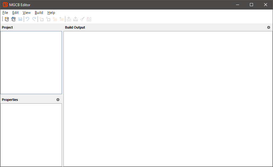
Look in the Content folder of your solution explorer in Visual Studio. You should also notice a file, Content.mgcb in the same folder. This is a listing of all content to bring into the game. Go ahead and open it; it will look something like:

The MGCB Editor The MGCB Editor

Tip

If instead of the editor program a text file is loaded in your VisualStudio instance, try right-click the file and choose “open with”. From the dialog, choose the mgcb-editor-wpf. If it is not listed, you may need to install it. From the command line:

> dotnet tool install --global dotnet-mgcb-editor 
> mgcb-editor --register

Click the “Add Existing Item” toolbar button:

Add Existing Item toolbar button Add Existing Item toolbar button

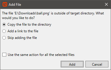
In the Open dialog that appears, select the ball image and click “Open”. Then in the next dialog, choose “Copy the file to the directory”:

Add File Dialog Add File Dialog

Finally, save the .mgcb file:

Save the .mgcb file Save the .mgcb file

Now the image will be built into a game-specific binary format as part of the build process. We’ll delve deeper into how this works in the chapter on the Content Pipeline.

LoadContent() Additions

To bring the ball texture into the game, we need to load it with a ContentManager class by invoking the ContentManager.Load<T>() method with the name of our content. The Game class has one already created and ready in the Game.Content property; we’ll use it:

_ballTexture = Content.Load<Texture2D>("ball");

Add this line just below the #TODO: use this.Content to load your game content here line in the LoadContent() method.

Note that we use the filename (sans extension) to identify the content file to load, and that we also specify the type of object it should be loaded as (in this case, Texture2D).

At this point, if we were to run the game everything would be initialized. Now we need to handle updating and rendering the game world.

The Update Method

As we mentioned before, the virtual Game.Update(GameTime gameTime) method is a hook for adding your game’s logic. By overriding this method, and adding your own game logic code, you fulfill the update step of the game loop.

This is where you place the simulation code for your game - where the world the game is representing is updated. Here, all your actors (the parts of the game world that move and interact) are updated.

Note the GameTime parameter - it provides us with both the total time the game has been running, and the time that has elapsed between this and the previous step through the game loop (the frame). We can use this in our physics calculations.

Our Simple Example

So in our example, we want the ball to move around the screen, according to its velocity. If you remember your physics, the velocity is the change in position over time, i.e.:

$ \overrightarrow{p'} = \overrightarrow{p} + \overrightarrow{v} * t $

We can express this in C# easily:

_ballPosition += _ballVelocity * (float)gameTime.ElapsedGameTime.TotalSeconds;

Add this code to the Update() method, just below the // TODO statement. Note that MonoGame provides operator overrides for performing algebraic operations on Vector2 structs, which makes writing expressions involving vectors very much like the mathematical notation. Also, note again that we have to cast the double TotalSeconds into a float as we are loosing some precision in the operation.

Also, note that because we multiply the velocity by the elapsed time, it does not matter what our timestep is - the ball will always move at the same speed. Had we simply added the velocity to the position, a game running with a 60fps timestep would be twice as fast as one running at 30fps.

Info

You may encounter advocates of using a hard-coded fixed time step to avoid calculations with elapsed time. While it is true this approach makes those calculations unnecessary (and thus, makes your code more efficient), you are trading off the ability of your game to adjust to different monitor refresh rates. In cases where your hardware is constant (i.e. the Nintendo Entertainment System), this was an easy choice. But with computer games, I would advocate for always calculating with the elapsed time.

Keeping the Ball on-screen

We need to handle when the ball moves off-screen. We said we wanted to make it bounce off the edges, which is pretty straightforward. First, we need to determine if the ball is moving off-screen. To know when this would happen, we need to know two things:

  1. The coordinates of the ball
  2. The coordinates of the edges of the screen

For 1, we have _ballPosition. Let’s assume this is the upper-right corner of the ball image. We’ll also need to factor in the size of the ball. The image linked above is 64 pixels, so I’ll assume that is the size of the ball we’re using. Feel free to change it to match your asset.

For 2, we can use GraphicsDevice.Viewport to get a rectangle defining the screen.

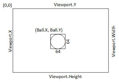
It can be very helpful to draw a diagram of this kind of setup before you try to derive the necessary calculations, i.e.:

A diagram of the game A diagram of the game

To check if the ball is moving off the left of the screen, we could use an if statement:

if(_ballPosition.X < GraphicsDevice.Viewport.X) {
    // TODO: Bounce ball
}

We could then reverse the direction of the ball by multiplying its velocity in the horizontal plane by $ -1 $:

    _ballVelocity.X *= -1;

Moving off-screen to the right would be almost identical, so we could actually combine the two into a single if-statement:

    // Moving offscreen horizontally
    if (_ballPosition.X < GraphicsDevice.Viewport.X || _ballPosition.X > GraphicsDevice.Viewport.Width - 64)
    {
        _ballVelocity.X *= -1;    
    }

Note that we need to shorten the width by 64 pixels to keep the ball on-screen.

The vertical bounce is almost identical:

    // Moving offscreen vertically
    if (_ballPosition.Y < GraphicsDevice.Viewport.Y || _ballPosition.Y > GraphicsDevice.Viewport.Height - 64)
    {
        _ballVelocity.Y *= -1;
    }
Info

Our bounce here is not quite accurate, as the ball may have moved some pixels off-screen before we reverse the direction.
In the worst case, it will actually so far off screen that with floating point error, it might be off-screen next frame as well (which will result in it getting stuck). But as long as our ball is traveling less than its dimensions each frame, we should be okay.

Now we just need to draw our bouncy ball.

The Draw Method

The Game.Draw(Game.Update(GameTime gameTime) method is a another hook, this one for adding your game’s rendering code. By overriding this method, and adding your own rendering code, you fulfill the draw step of the game loop.

MonoGame uses the graphics hardware to render the scene, along with double buffering. Thus, when we render, we are drawing into a back buffer, and once that drawing is complete, we flip the buffers so that the one we just finished is what ends up being rendered on-screen, and we now can start drawing into the next back buffer.

This is why we request a certain window size by setting Game.PreferredBackBufferWidth and Game.PreferredBackBufferHeight. It is an acknowledgement that we are working with the back buffer (all buffers end up this size). If our window’s client area is a different size, then the texture the back buffer contains is scaled to fit the client dimensions. If this is not the same aspect ratio, our game will appear squished in one dimension and stretched in the other.

This is why resizing the window is disabled by default in MonoGame. If you let the user resize the window, you’ll want to also adjust your buffers to compensate.

Our Simple Example

Our game is two-dimensional. Since MonoGame uses the 3D rendering hardware, this means we’re really pretending a 3D scene is two-dimensional. You might think of it as a bunch of cardboard cut-outs all facing the audience. To make life easier for us, MonoGame provides the SpriteBatch class to manage all of those cut-outs.

We’ll dig deeper into how it works in a later chapter. But for now, know that we can render any number of images on-screen by invoking SpriteBatch.Draw() between a SpriteBatch.Begin() and a SpriteBatch.End() invocation.

For our simple ball, this breaks down to:

    _spriteBatch.Begin();            
    _spriteBatch.Draw(_ballTexture, _ballPosition, Color.White);
    _spriteBatch.End();

Effectively, we’re saying we want to draw our texture _ballTexture at _ballPosition, and apply a white color to the image (i.e. leave it the color it already is).

This should be placed after the // TODO in the Base We're going to be rendering with the SpriteBatch` class.

That wraps up our simple exercise. You should be able to run the game now, and see the ball bounce around the screen.

Summary

In this chapter we looked at how MonoGame implements the Game Loop pattern within its Game class. We also saw how the Game class interacts with the GameWindow class, which provides an abstraction of the operating system’s window representation. We saw how we can add our own custom code into the MonoGame game loop by overriding the Game.Update() and Game.Draw() methods, as well as the overriding Game.Initialize() and Game.LoadContent() to set up the game world.

We briefly explored ideas about performing physics calculations within that game world, as well as representing position and velocity of game actors with Vector2 objects. We also touched on how MonoGame renders 2D games with 3D hardware, and used a SpriteBatch instance to render a Texture2D to the screen. Finally, we animated a bouncing ball using all of these ideas. The one aspect of the game loop we did not cover though, is input, which we’ll take a look at in the next chapter.

Player Input

Need Input! Need Input Need Input

Subsections of Player Input

Introduction

By this point you have probably built a lot of programs with user interfaces. Most, or possibly all, were written in an event-driven fashion, i.e. you created a method to serve as an event handler, i.e.:

public void OnButtonPress(object sender, EventArgs e)
{
    // Your logic here...
}

This approach is a good fit for most productivity desktop applications. After all, most of the time your text editor is just waiting for you to do something interesting - like move the mouse or type a letter. During this waiting period, it doesn’t need to do anything else - what is on-screen isn’t changing, what it has stored internally isn’t changing. It basically spends most of its time waiting.

Most games, on the other hand, are never waiting. They are real-time simulations of a world. The Goomba will keep walking, the Bullet Bill flying, and the Piranha Plant popping in and out of pipes whether or not Mario moves. Hence the game loop - each update and render cycle updates the state of the game world, and then renders that updated world.

While event-driven programming is extremely efficient in a desktop application that waits on user input most of the time, it is problematic in a real-time game. Hence, the process input stage in the game loop from Game Programming Patterns:

The Game Loop The Game Loop

But what exactly does that step entail? Let’s find out.

Input Polling

Instead of letting the OS tell us when an input event occurs (as we do with event-driven programming), in the game loop we use device polling with the input devices. This means that we ask the device for its current state when we start processing user input.

Consider a gamepad with a button, A. We can represent such a button with a boolean value; true if it is pressed, and false if it is not. Thus, the classic NES controller could be represented by a struct composed entirely of booleans:

public struct NESPad 
{
    // The D-Pad
    public bool Up;
    public bool Down;
    public bool Left;
    public bool Right;

    // The Buttons
    public bool A;
    public bool B;
    public bool Start;
    public bool Select;
}

At the start of each iteration of the game loop, we could gather the current state and assign it to a copy of this struct, say PlayerOneInput. We would then use it in the Update() method:

public void Update(GameTime gameTime)
{
    if(PlayerOneInput.Left) 
    {
        PlayerPosition.X += Speed * gameTime.ElapsedGameTime.TotalSeconds;
    }
}

That works well for continuous actions like walking, but what about discrete ones like jumping? Remember, your game is updating at 1/30th or 1/60th of a second. No player is so fast that they only hold down a button for 1/60th of a second. Instead, they’ll hold it down for several frames, even when they meant to just tap it. If our jump logic is something like:

    if(PlayerOneInput.A) Jump();

We’ll end up calling that Jump() method multiple frames in a row!

The solution is to keep two structs: one with the current frame’s input, and one with the prior frames, i.e.:

NESPad currentPlayerOneInput;
NESPad priorPlayerOneInput;

public void Update()
{
    if(currentPlayerOneInput.A && !priorPlayerOneInput.A) {
        // The A button was just pressed this frame, so Jump!
        Jump();
    }
}

That wraps up using the input, but how about getting it in the first place? That’s what the process input stage in the game loop is about. But you’ve probably noticed that your MonoGame Game class doesn’t have a corresponding method…

This is because XNA was built to handle four XBox 360 gamepads (as you would see on an XBox 360), as well as keyboard and mouse input out of the box. And MonoGame added support for Joysticks and expanded the number and kind of gamepads that could be used. The process input stage is there - we just don’t need to see it. Instead, we can grab the already-polled input data with one of the static input classes. We’ll take a look at each of these next.

Keyboard Input

Let’s start with the keyboard. MonoGame uses the KeyboardState struct to represent the state of a keyboard. It is essentially a wrapper around an array of bits - one for each key in a standard keyboard. The indices of each key are represented by the Keys enumeration (you can find a complete listing in the docs).

We get the current state of the keyboard with the static Keyboard’s GetState() method, which returns the aforementioned KeyboardState struct. Thus, if we wanted to have current and prior keyboard states, we’d add fields to hold them:

private KeyboardState priorKeyboardState;
private KeyboardState currentKeyboardState;

And within our Update(GameTime gameTime) method, we’d first copy the current (but now old) state to the prior variable, and then grab the updated state for the current variable:

public override void Update(GameTime gameTime) 
{
    priorKeyboardState = currentKeyboardState;
    currentKeyboardState = Keyboard.GetState();

    // TODO: Your update logic goes here...

    base.Update(gameTime);
}

The KeyboardState struct contains properties:

  • Keys - an array of 256 bits, with each bit corresponding to a particular key
  • CapsLock - a boolean indicating if the caps lock is on
  • NumLock - a boolean indicating if the num lock is on

But more often, we’ll use its method IsKeyDown(Keys key) or IsKeyUp(Keys key), both of which take a Keys value. For example, we can check if the escape key is pressed with:

    if(currentKeyboardState.IsKeyDown(Keys.Escape))
    {
        // Escape key is down
    }

And, if we need to determine if a key was just pressed this frame, we would use:

    if(currentKeyboardState.IsKeyDown(Keys.I) &&
         priorKeyboardState.IsKeyUp(Keys.I))
    {
        // The I key was just pressed this frame
    }

Similarly, to see if a key was just released this frame, we would reverse the current and previous conditions:

    if(currentKeyboardState.IsKeyUp(Keys.I) &&
        priorKeyboardSate.IsKeyDown(Keys.I))
    {
        // The I key was just released this frame
    }
Info

Note that part of the reason we use a struct instead of a Class for our state is that a struct is a value type, i.e. it allocates exactly the space need to store its data, and when we set it equal to a different struct instance, i.e.:

    priorKeyboardState = currentKeyboardState;

What actually happens is we copy the bits from currentKeyboardState over the top of priorKeyboardState. This is both a fast operation and it allocates no additional memory - ideal for the needs of a game. This is also why so many of MonoGame’s data types are structs instead of classes.

Mouse Input

Mouse input works much like keyboard input - we have a MouseState struct that represents the state of the mouse, and we can get the current state from the static Mouse class’s GetState() method. You’ll also want to use the same caching strategy of a current and prior state if you want to know when a button goes down or comes up, i.e.:

    MouseState currentMouseState;
    MouseState priorMouseState;

    public override void Update(GameTime gameTime) 
    {
        priorMouseState = currentMouseState;
        currentMouseState = Mouse.GetState();

        // TODO: Add your update logic here 

        base.Update(gameTime);
    }

However, the MouseState struct has a different set of properties:

  • X - the horizontal position of the mouse as an integer in relation to the window.
  • Y - the vertical position of the mouse as an integer in relation to the window.
  • LeftButton - a ButtonState indicating if the left button is down
  • MiddleButton - a ButtonState indicating if the middle button is down
  • RightButton - a ButtonState indicating if the right button is down
  • ScrollWheelValue - an integer representing the cumulative scroll wheel value since the start of the game
  • HorizontalScrollWheelValue - an integer representing the cumulative scroll wheel value since the start of the game
  • XButton1 - a ButtonState indicating if the XButton1 button is down
  • XButton2 - a ButtonState indicating if the XButton2 is down

Note that instead of booleans, buttons are represented by the ButtonState enumeration. This allows the internal representation of the MouseState buttons to be a single bitmask, making copy operations on the MouseState much faster (and the struct itself to take up less space).

Thus, to check if the LeftButton is down, we’d need to use:

if(currentMouseState.LeftButton == ButtonState.Pressed) 
{
    // left mouse button is pressed.
}
Info

Note that not all mice have all of these possible inputs - the Horizontal scroll wheel and X buttons, especially, but many mice also lack the middle button and scroll wheel. In those cases these values will be ButtonState.Released or false.

The Mouse Cursor

You can set what cursor the mouse should use with the Mouse.SetCursor(MouseCursor cursor), and supply the cursor of your choice, i.e. MouseCursor.Crosshair. A full list of cursors can be found in the documentation.

You can also create a cursor from a texture with MouseCursor.FromTexture2D(Texture2D texture, int originX, int originY). The Texture2D is loaded with a ContentManager, just as we did in our HelloGame example. The originX and originY describe where the mouse pointer is in relation to the upper-left-hand corner of the image.

You can also hide the mouse cursor by setting the Game.IsMouseVisible property to false.

Gamepad Input

MonoGame handles gamepad input in a similar fashion to Keyboard and Mouse input. For example, there is a static GamePad class and a GamePadState struct.

Player Indices

However, XNA was originally designed to work with the XBox 360, which supported up to four players connected through XBox 360 gamepads. Thus, instead of using GamePad.GetState() we would use GamePad.GetState(PlayerIndex playerIndex), where the PlayerIndex enumeration value corresponded to which player’s gamepad we wanted to poll.

However, MonoGame can (in theory) support more than four gamepads, so it also added a GamePad.GetState(int index). You can find out how many gamepads are supported on your system with the property GamePad.MaxiumumGamePadCount.

Thus, to get the first gamepad’s state, we would:

    GamePadState currentGamePadState;
    GamePadState priorGamePadState;

    public override void Update(GameTime gameTime) 
    {
        priorGamePadState = currentGamePadState;
        currentGamePadState = GamePad.GetState(1);

        // TODO: Add your update logic here 

        base.Update(gameTime);
    }

GamePad Capabilities and Types

Also, the XBox controller had a standardized number of buttons and triggers, but MonoGame supports a wider variety of gamepads. You can check the capabilities of any connected pad with GamePad.GetCapabilities(int index), which returns a GamePadCapabilities struct, i.e.:

GamePadCapabilities capabilities = GamePad.GetCapabilities(1);

The GamePadType property is one of the GamePadType enumeration values, which include options like the various Rock band/Guitar hero instruments, dance pads, arcade sticks, flight sticks, and wheels. Note that each of these types still provide their input through standard button and axis properties.

The various other properties of the GamePadCapabilities are booleans corresponding to different types of buttons pads, and sticks. You can see them all listed in the documentation.

GamePadState

The GamePadState is actually implemented as a partial struct, so additional data can be added based on the platform. The various buttons, pads, and sticks are broken out into individual sub-structs.

Buttons

For example, the GamePadState.Buttons property is a GamePadButtons struct representing the traditional buttons (those that are either pressed or not - A, B, X, Y, Start, Back, Big Button, Left Shoulder, Right Shoulder, Left Stick, Right Stick). As with the mouse buttons we saw before, these are represented using the ButtonState enum. Thus, to determine if the A button is pressed, we would use:

    if(currentGamePadState.Buttons.A == ButtonState.Pressed)
    {
        // A button is pressed
    }

And to determine if the X button was _just pressed this frame:

    if(currentGamePadState.Buttons.X == ButtonState.Pressed 
    && priorGamePadState.Buttons.X == ButtonState.Released)
    {
        // X button was just pressed this frame
    }

DPad

The GamePadState.DPad property is a GamePadDPad struct, also composed of ButtonValues for the four directions of the DPad (Up, Down, Left, Right). I.e. to check if the right direction pad button is pressed:

    if(currentGamePadState.DPad.Right == ButtonState.Pressed)
    {
        // Right Dpad button is pressed
    }

Triggers

The GamePadState.Triggers property is a GamePadTriggers struct representing the two triggers (Left and Right). Unlike other buttons, these measure the travel, or the amount of pull that has been applied to them. Thus, they are represented by a single floating point number between 0 and 1.

To see if the left trigger is pulled back 3/4 of the way, we might use:

    if(currentGameState.Triggers.Left > 0.75)
    {
        // Left Trigger is pulled at least 3/4 of the way back
    }

ThumbSticks

The GamePadState.Thumbsticks property is a GamePadThumbSticks struct representing the two thumbsticks (Left and Right). These are represented by Vector2 values with the X and Y falling between -1 and 1.

Thus, to get where the right thumbstick is pointing, we might use:

    Vector2 direction = GamePad.Thumbsticks.Right;

IsButtonDown/IsButtonUp

The GamePadState also implements convenience functions IsButtonUp(Button button) and IsButtonDown(Button button) that operate like the keyboards’ equivalents.

Vibration

Many gamepads come equipped with two vibration-inducing motors (left and right). These are exposed through the GamePad.SetVibration(int index, single left, single right) method, where you can set a vibration in either motor using a floating point value between 0 and 1.

Thus, to start vibration in both of player one’s gamepad’s motors at half-strength, you would use:

GamePad.SetVibration(0, 0.5f. 0.5f);

To stop them you would need to send:

GamePad.SetVibration(0, 0, 0);

Input Manager

At this point, you may be noticing that our input processing could quickly dominate our Game class, and can be very messy. Especially if we want to support multiple forms of input in the same game. Consider if we wanted to do a platformer - we might want the player to be able to use the keyboard or a gamepad.

One technique we can employ is an input manager, a class that handles polling the input and abstracts it to just the commands we care about. I.e. for a simple platformer, we might want the four directions and “jump”.

We can create a class called InputManager that would provide those:

using Microsoft.Xna.Framework;
using Microsoft.Xna.Framework.Input;

/// <summary>
/// Manages input for a simple platformer
/// </summary>
public class InputManager 
{
    /// <summary>
    /// The player's direction
    /// </summary>
    public Vector2 Direction { get; private set; }

    /// <summary>
    /// If the player pressed jump this frame 
    /// </summary>
    public bool Jump { get; private set; }
}

Note that we use public auto-properties, but override the set to be private. This way outside code can access these boolean properties, but only the code in this class can set them.

We’ll also need to declare our state variables:

    /// Input state variables
    private KeyboardState currentKeyboardState;
    private KeyboardState priorKeyboardState;
    private GamePadState currentGamePadState;
    private GamePadState priorGamePadState;

And, we’ll process these in an update method:

    /// <summary>
    /// Update the input object
    /// </summary>
    /// <param name="gameTime">The game time</param>
    public void Update(GameTime gameTime)
    {
        // Update input state
        priorKeyboardState = currentKeyboardState;
        currentKeyboardState = Keyboard.GetState();
        priorGamePadState = currentGamePadState;
        currentGamePadState = GamePad.GetState(0);

        // TODO: Assign actions based on input
    }

This looks just like how we updated state before. The next step is to abstract the input into the properties we defined. We’ll start with the Direction, which we are using a Vector2 to represent. This conveniently matches with our gamepad’s thumbstick representation, so we can assign it directly:

    // Right thumbstick
    Direction = currentGamePadState.Thumbsticks.Right;

If there is no gamepad available, this will be the vector $ (0,0) $. Then we can check the WASD keys, and assign a corresponding value

    // WASD keys:
    if (currentKeyboardState.IsKeyDown(Keys.W)) Direction += new Vector2(0,-1);
    if (currentKeyboardState.IsKeyDown(Keys.A)) Direction += new Vector2(-1, 0);
    if (currentKeyboardState.IsKeyDown(Keys.S)) Direction += new Vector2(0,1);
    if (currentKeyboardState.IsKeyDown(Keys.D)) Direction += new Vector2(1, 0);

Note that we are adding a unit vector to the (supposedly zero) existing vector. This does mean that a player using both keyboard and mouse could double the direction vector length, so if this is important in your game you’ll need additional logic to prevent it.

For the jump, we want that to be a discrete push, i.e. it is only true the frame the button is pushed. So we’ll first need to reset it to false (in case it was true in a prior frame):

    // reset jump
    Jump = false;

Now we can check if the “A” button is pressed:

    if(currentGamePadState.IsButtonDown(Buttons.A) &&  priorGamePadState.IsButtonUp(Buttons.A))
        Jump = true;

Similarly, we can check for the spacebar:

    if(currentKeyboardState.IsKeyDown(Keys.Space) && priorKeyboardState.IsKeyUp(Keys.Space))
        Jump = true;

Now, we just need to construct an instance of InputManager in our game, invoke its Update() at the start of our game class’ Update() method, and then we can use the Direction and Jump properties to determine what should happen in our game.

This idea can be adapted to any game you want to make - but it will always be specific to the game, as what the controls need to do will vary from game to game. It also makes it easier to allow for multiple forms of input, and to also do user-controlled input mapping, where users can reassign keys/buttons to corresponding actions.

Input State

The Game State Management Sample provides a contrasting approach to the input manager. Instead of being tailored to a specific game, it seeks to provide generic access to all input information. It also handles multiplayer input, and can be used to manage when a player switches gamepads. A simplified form (which does not handle gestural input) is provided below.

In particular, the IsButtonPressed(Buttons button, PlayerIndex? controllingPlayer, out PlayerIndex playerIndex) can check for a key press on any connected keyboard, or identify what player’s keyboard was the source of the input. And the IsNewButtonPress(Buttons button, PlayerIndex? controllingPlayer, out PlayerIndex playerIndex) is handled the same way, but detects new button presses.

There are also equivalents for keyboard input.

// Helper for reading input from keyboard, gamepad, and touch input. This class 
// tracks both the current and previous state of the input devices, and implements 
// query methods for high level input actions such as "move up through the menu"
// or "pause the game".
public class InputState
{
    private const int MaxInputs = 4;

    public readonly KeyboardState[] CurrentKeyboardStates;
    public readonly GamePadState[] CurrentGamePadStates;

    private readonly KeyboardState[] _lastKeyboardStates;
    private readonly GamePadState[] _lastGamePadStates;

    public readonly bool[] GamePadWasConnected;
    
    public InputState()
    {
        CurrentKeyboardStates = new KeyboardState[MaxInputs];
        CurrentGamePadStates = new GamePadState[MaxInputs];

        _lastKeyboardStates = new KeyboardState[MaxInputs];
        _lastGamePadStates = new GamePadState[MaxInputs];

        GamePadWasConnected = new bool[MaxInputs];
    }

    // Reads the latest user input state.
    public void Update()
    {
        for (int i = 0; i < MaxInputs; i++)
        {
            _lastKeyboardStates[i] = CurrentKeyboardStates[i];
            _lastGamePadStates[i] = CurrentGamePadStates[i];

            CurrentKeyboardStates[i] = Keyboard.GetState();
            CurrentGamePadStates[i] = GamePad.GetState((PlayerIndex)i);

            // Keep track of whether a gamepad has ever been
            // connected, so we can detect if it is unplugged.
            if (CurrentGamePadStates[i].IsConnected)
                GamePadWasConnected[i] = true;
        }
    }

    // Helper for checking if a key was pressed during this update. The
    // controllingPlayer parameter specifies which player to read input for.
    // If this is null, it will accept input from any player. When a keypress
    // is detected, the output playerIndex reports which player pressed it.
    public bool IsKeyPressed(Keys key, PlayerIndex? controllingPlayer, out PlayerIndex playerIndex)
    {
        if (controllingPlayer.HasValue)
        {
            // Read input from the specified player.
            playerIndex = controllingPlayer.Value;

            int i = (int)playerIndex;

            return CurrentKeyboardStates[i].IsKeyDown(key);
        }

        // Accept input from any player.
        return IsKeyPressed(key, PlayerIndex.One, out playerIndex) ||
                IsKeyPressed(key, PlayerIndex.Two, out playerIndex) ||
                IsKeyPressed(key, PlayerIndex.Three, out playerIndex) ||
                IsKeyPressed(key, PlayerIndex.Four, out playerIndex);
    }

    // Helper for checking if a button was pressed during this update.
    // The controllingPlayer parameter specifies which player to read input for.
    // If this is null, it will accept input from any player. When a button press
    // is detected, the output playerIndex reports which player pressed it.
    public bool IsButtonPressed(Buttons button, PlayerIndex? controllingPlayer, out PlayerIndex playerIndex)
    {
        if (controllingPlayer.HasValue)
        {
            // Read input from the specified player.
            playerIndex = controllingPlayer.Value;

            int i = (int)playerIndex;

            return CurrentGamePadStates[i].IsButtonDown(button);
        }

        // Accept input from any player.
        return IsButtonPressed(button, PlayerIndex.One, out playerIndex) ||
                IsButtonPressed(button, PlayerIndex.Two, out playerIndex) ||
                IsButtonPressed(button, PlayerIndex.Three, out playerIndex) ||
                IsButtonPressed(button, PlayerIndex.Four, out playerIndex);
    }


    // Helper for checking if a key was newly pressed during this update. The
    // controllingPlayer parameter specifies which player to read input for.
    // If this is null, it will accept input from any player. When a keypress
    // is detected, the output playerIndex reports which player pressed it.
    public bool IsNewKeyPress(Keys key, PlayerIndex? controllingPlayer, out PlayerIndex playerIndex)
    {
        if (controllingPlayer.HasValue)
        {
            // Read input from the specified player.
            playerIndex = controllingPlayer.Value;

            int i = (int)playerIndex;

            return (CurrentKeyboardStates[i].IsKeyDown(key) &&
                    _lastKeyboardStates[i].IsKeyUp(key));
        }

        // Accept input from any player.
        return IsNewKeyPress(key, PlayerIndex.One, out playerIndex) ||
                IsNewKeyPress(key, PlayerIndex.Two, out playerIndex) ||
                IsNewKeyPress(key, PlayerIndex.Three, out playerIndex) ||
                IsNewKeyPress(key, PlayerIndex.Four, out playerIndex);
    }

    // Helper for checking if a button was newly pressed during this update.
    // The controllingPlayer parameter specifies which player to read input for.
    // If this is null, it will accept input from any player. When a button press
    // is detected, the output playerIndex reports which player pressed it.
    public bool IsNewButtonPress(Buttons button, PlayerIndex? controllingPlayer, out PlayerIndex playerIndex)
    {
        if (controllingPlayer.HasValue)
        {
            // Read input from the specified player.
            playerIndex = controllingPlayer.Value;

            int i = (int)playerIndex;

            return CurrentGamePadStates[i].IsButtonDown(button) &&
                    _lastGamePadStates[i].IsButtonUp(button);
        }

        // Accept input from any player.
        return IsNewButtonPress(button, PlayerIndex.One, out playerIndex) ||
                IsNewButtonPress(button, PlayerIndex.Two, out playerIndex) ||
                IsNewButtonPress(button, PlayerIndex.Three, out playerIndex) ||
                IsNewButtonPress(button, PlayerIndex.Four, out playerIndex);
    }
}

Summary

In this chapter we learned about input polling and how it is implemented in XNA using structures representing input state and static GetState() methods. We saw the three primary forms of input we use in the MonoGame framework - the keyboard, the mouse, and the gamepad.

We also saw how a variety of game controllers (i.e. RockBand gear, steering wheels, flight sticks, etc.) are mapped to the standard gamepad; how its state struct is actually composed of several sub-structs; and how to turn on and off the vibration motors.

Finally, we discussed how we can use two copies of a state struct - one from the prior frame and one from the current frame - to determine if a button was just pressed or released.

Sprites

Who are you calling a fairy?

Subsections of Sprites

Introduction

The term “sprite” refers to a graphical element within a two-dimensional game that moves around the screen - often representing a character, powerup, or other actor. The term likely was coined in relation to its older definition - a small fairy creature.

Traditionally, sprites are a part of two-dimensional games, and are a raster graphic (one composed of a regular grid of pixels, aka a bitmap). As the sprites are simply an array of bits representing pixels, and the scene being presented on screen is also just an array of bits representing pixels, we can place a sprite on-screen by simply copying its bits into the right location.

Hardware Sprites

The earliest implementations of sprites did this by substituting the sprite bits for background image bits as the bits were streamed to the screen as part of an analog frame signal. This was done by specialized hardware that supported a limited number of sprites (hence the name hardware sprites).

Bit Blitting

Later games used bit blitting (an abbreviation for bit-boundary block transfer), a technique for copying a smaller bit array into a larger one. Early graphics hardware implemented bit blitting as a hardware instruction, meaning it could be performed very fast, provided the sprite was drawn to scale.

Textured Quads

Modern games (and MonoGame) often use the 3D hardware to render sprites, which means they are represented as textured quads. A textured quad is essentially a rectangle composed of two triangles that always faces the screen.

While it is more complex than traditional sprites, there are several benefits to this approach:

  1. It is far easier to scale sprites composed as textured quads than bit-blitted sprites (and scaling is impossible with most hardware sprites)
  2. Textured Quad sprites can be rotated to an arbitrary angle using the graphics hardware. Bit-blitted sprites could only be flipped (mirrored) in the X or Y direction, true rotations required additional sprite images drawn from the desired angle
  3. Textured Quad sprites can take advantage of the Z-buffer to do depth sorting. Traditional bit-blitted sprites had to be drawn using the painters algorithm or similar techniques to ensure proper layering.
  4. Textured sprites are rendered using shader programs on the graphics card, so many unique effects can be applied to them.

In this chapter, we’ll examine how the MonoGame implementation of textured quads works.

Drawing Sprites

MonoGame provides the SpriteBatch class to help mitigate the complexity of implementing textured quad sprites. It provides an abstraction around the rendering process that lets us render sprites with a minimum of fuss, with as much control as we might need.

As the name suggests, the SpriteBatch batches sprite draw requests so that they can be drawn in an optimized way. We’ll explore the different modes we can put the SpriteBatch in soon. But for now, this explains why every batch begins with a call to SpriteBatch.Begin(), then an arbitrary number of SpriteBatch.Draw() calls, followed by a SpriteBatch.End() call.

We’ve already used this pattern in our Hello Game example from chapter 1:

    _spriteBatch.Begin();            
    _spriteBatch.Draw(_ballTexture, _ballPosition, Color.White);
    _spriteBatch.End();

In this example, we draw a single sprite, using the _ballTexture, and drawing the graphic it represents with the upper-right corner at _ballPosition, and blend white (Color.White) with the sprite texture’s own colors.

The SpriteBatch.Draw() method actually has a seven available overrides for your use:

  • public void Draw(Texture2D texture, Rectangle destinationRectangle, Color color)
  • public void Draw(Texture2D texture, Rectangle destinationRectangle, Rectangle? sourceRectangle, Color color)
  • public void Draw(Texture2D texture, Rectangle destinationRectangle, Rectangle? sourceRectangle, Color color, float rotation, Vector2 origin, SpriteEffects effects, float layerDepth)
  • Draw(Texture2D texture, Vector2 position, Color color)
  • Draw(Texture2D texture, Vector2 position, Rectangle? sourceRectangle, Color color)
  • Draw(Texture2D texture, Vector2 position, Rectangle? sourceRectangle, Color color, float rotation, Vector2 origin, Vector2 scale, SpriteEffects effects, float layerDepth)
  • Draw(Texture2D texture, Vector2 position, Rectangle? sourceRectangle, Color color, float rotation, Vector2 origin, float scale, SpriteEffects effects, float layerDepth)

Rather than explain each one individually, we’ll explore what the various parameters are used for, and you can select the one that matches your needs.

Texture2D texture

The texture parameter is a Texture2D containing the sprite you want to draw. Every override includes this parameter. If the texture has not been loaded (is null), then invoking Draw() will throw an ArgumentNullException.

Rectangle destinationRectangle

The destinationRectangle is a rectangle whose coordinates are where the sprite should be drawn, in screen coordinates. If the rectangle’s dimensions are not the same as those of the source image (or the sub-image specified by sourceRectangle), it will be scaled to match. If the aspect ratios are different, this will result in a stretched or squished sprite. Note that the Rect uses integers for coordinates, so calculated floats used to place the sprite will potentially be truncated.

Color color

The color parameter is a Color that will be blended with the colors in the texture to determine the final color of the sprite. Using Color.White effectively keeps the texture color the same, while using Color.Red will make the sprite’s pixels all redder, Color.Yellow will make them more yellow, etc. This parameter can be utilized to make the sprite flash different colors for damage, invulnerability, etc.

Vector2 position

As an alternative to the destinationRectangle, a sprite’s position on-screen can be specified with position, which is a Vector2. This position specifies the upper-left hand corner of where the sprite will be drawn on-screen (unless the origin parameter is set). Note that when we use the position parameter, the width and height matches that of the texture (or sub-image specified by the sourceRectangle), unless a scale is also provided.

Rectangle? sourceRectangle

The sourceRectangle is a rectangle that defines a subarea of the source texture (texture) to use as the sprite. This is useful for texture atlases, where more than one sprite appear in the same texture, and also for sprite animation where multiple frames of animation appear in the same texture. We’ll discuss both of these approaches soon.

Note that the question mark in Rectangle? indicates it is a nullable type (i.e. it can be null as well as the Rectangle struct). When it is null, the entire texture is used as the sourceRectangle.

float rotation

The rotation is a rotation value measured in radians that should be applied to the sprite. This is one of the big benefits of textured quad sprites, as the graphics hardware makes rotations a very efficient operation (without this hardware, it becomes a much more difficult and computationally expensive operation). This rotation is about the origin of the sprite, which is why all the overrides that specify the rotation also specify the origin.

Vector2 origin

The origin is the spot within the sprite where rotations and scaling are centered. This also affects sprite placement - the position vector indicates where the origin of the sprite will fall on-screen. It is a vector measured relative to the upper-left-hand-corner of the sprite, in texture coordinates (i.e. pixels of the source texture).

Thus, for our 64x64 pixel ball texture, if we wanted the origin to be at the center, we would specify a value of new Vector2(32,32). This would also mean that when our ball was at position $ (0,0) $, it would be centered on the origin and 3/4 of the ball would be off-screen.

float scale

The scale is a scalar value to scale the sprite by. For example, a value of $ 2.0f $ will make the sprite twice as big, while $ 0.5f $ would make it half as big. This scaling is in relation to the origin, so if the origin is at the center of the sprite grows in all directions equally. If instead it is at $ (0,0) $, the sprite will grow to the right and down only.

Vector2 scale

The scale can also be specified as a Vector2, which allows for a different horizontal and vertical scaling factor.

SpriteEffects effects

The effects parameter is one of the SpriteEffects enum’s values. These are:

  • SpriteEffects.None - the sprite is drawn normally
  • SpriteEffects.FlipHorizontally - the sprite is drawn with the texture flipped in the horizontal direction
  • SpriteEffects.FlipVertically - the sprite is drawn with the texture flipped in the vertical direction

Note you can specify both horizontal and vertical flipping with a bitwise or: SpriteEffects.FlipHorizontally | SpriteEffects.FlipVertically

single layerDepth

The layerDepth is an integer that indicates which sprites should be drawn “above” or “below” others (i.e. which ones should obscure the others). Think of it as assembling a collage. Sprites with a higher layerDepth value are closer to the top, and if they share screen space with sprites with a lowerDepth, those sprites are obscured.

Texture Atlases

A texture atlas is a texture that is used to represent multiple sprites. For example, this texture from Kinney’s 1Bit Pack available on OpenGameArt contains all the sprites to create a roguelike in a single texture:

Kinney’s 1Bit Pack Texture Atlas Kinney’s 1Bit Pack Texture Atlas

In this case, each sprite is 15x15 pixels, with a 1 pixel outline. So to draw the cactus in the second row and sixth column of sprites, we would use a source rectangle:

var sourceRect = new Rectangle(16, 96, 16, 16);

Thus, to draw the sprite on-screen at position $ (50,50) $ we could use:

protected override void Draw(GameTime gameTime)
{
    GraphicsDevice.Clear(Color.CornflowerBlue);

    // TODO: Add your drawing code here
    spriteBatch.Begin();
    spriteBatch.Draw(atlas, new Vector2(50, 50), new Rectangle(96, 16, 15, 15), Color.White);
    spriteBatch.End();

    base.Draw(gameTime);
}

And we’d see:

The rendered sprite from the sprite atlas The rendered sprite from the sprite atlas

This texture atlas is laid out in 16x16 tiles, which makes calculating the X and Y of our source rectangle straightforward:

var x = xIndex * 16;
var y = yIndex * 16;

The formula involved for a particular texture atlas will depend on the size and spacing between sprites. Also, some texture atlases are not evenly spaced. In those cases, it may be useful to define a Rectangle constant for each one, i.e.

const Rectangle helicopterSource = new Rectangle(15, 100, 200, 80);
const Rectangle missileSource = new Rectangle(30, 210, 10, 3);
Info

The texture used in the above example has a brown background. If you would like to replace this with transparent black, you can set a color key color in the mgcb content editor. Any pixel this color in the source image will be turned into transparent black when the content is compiled. In this case, our color’s RGB values are (71, 45, 60):

Setting the Color Key Color Setting the Color Key Color

The result is that sprites rendered from the texture now have a transparent background:

The rendered sprite with a transparent background The rendered sprite with a transparent background

Animated Sprites

To animate a sprite, we simply swap the image it is using. Animated sprites typically lay out all their frames in a single texture, just like a texture atlas. Consider this animated bat sprite by bagzie from OpenGameArt:

Animated bat spritesheet Animated bat spritesheet

The images of the bat are laid out into a 4x4 grid of 32x32 pixel tiles. We can create the illusion of motion by swapping which of these images we display. However, we don’t want to swap it every frame - doing so will be too quick for the viewer to follow, and destroy the illusion. So we also need a timer and an idea of the direction the sprite is facing.

To represent the direction, we might define an enum. And since the enum can represent a numerical value, let’s assign the corresponding row index to each direction:

/// <summary>
/// The directions a sprite can face 
/// </summary>
public enum Direction {
    Down = 0,
    Right = 1,
    Up = 2, 
    Left = 3 
}

With this extra state to track, it makes sense to create a class to represent our sprite:

/// <summary>
/// A class representing a bat
// </summary>
public class BatSprite
{
    // The animated bat texture 
    private Texture2D texture;

    // A timer variable for sprite animation
    private double directionTimer;

    // A timer variable for sprite animation
    private double animationTimer;

    // The current animation frame 
    private short animationFrame;

    ///<summary>
    /// The bat's position in the world
    ///</summary>
    public Vector2 Position { get; set; }

    ///<summary>
    /// The bat's direction
    /// </summary>
    public Direction Direction { get; set; }
}

We’ll need a LoadContent() method to load our texture:

/// <summary>
/// Loads the bat sprite texture
/// </summary>
/// <param name="content">The ContentManager</param>
public void LoadContent(ContentManager content) 
{
    texture = content.Load<Texture2D>("32x32-bat-sprite.png");
}

Let’s make our bat fly in a regular pattern, switching directions every two seconds. To do this, we would want to give our bat an Update() method that updates a timer to determine when it is time to switch:

public void Update(GameTime gameTime) 
{
    // advance the direction timer
    directionTimer += gameTime.ElapsedGameTime.TotalSeconds;

    // every two seconds, change direction
    if(directionTimer > 2.0) 
    {
        switch(Direction)
        {
            case Direction.Up: 
                Direction = Direction.Down;
                break;
            case Direction.Down:
                Direction = Direction.Left;
                break;
            case Direction.Left:
                Direction = Direction.Right;
                break;
            case Direction.Right:
                Direction = Direction.Up;
                break;
        }
        // roll back timer 
        directionTimer -= 2.0;
    }

    // move bat in desired direction
    switch (Direction)
    {
        case Direction.Up:
            Position += new Vector2(0, -1) * 100 * (float)gameTime.ElapsedGameTime.TotalSeconds;
            break;
        case Direction.Down:
            Position += new Vector2(0, 1) * 100 * (float)gameTime.ElapsedGameTime.TotalSeconds;
            break;
        case Direction.Left:
            Position += new Vector2(-1, 0) * 100 * (float)gameTime.ElapsedGameTime.TotalSeconds;
            break;
        case Direction.Right:
            Position += new Vector2(1, 0) * 100 * (float)gameTime.ElapsedGameTime.TotalSeconds;
            break;
    }
}

We’ll use a similar technique to advance the animation frame - once every 16th of a second, in the Draw() method:

public void Draw(GameTime gameTime, SpriteBatch spriteBatch) {
    // advance the animation timer 
    animationTimer += gameTime.ElapsedGameTime.TotalSeconds;

    // Every 1/16th of a second, advance the animation frame 
    if(animationTimer > 1/16)
    {
        animationFrame++;
        if(animationFrame > 3) animationFrame = 0;
        animationTimer -= 1/16;
    }

    // Determine the source rectangle 
    var sourceRect = new Rectangle(animationFrame * 32, (int)Direction * 32, 32, 32);

    // Draw the bat using the current animation frame 
    spriteBatch.Draw(texture, Position, sourceRect, Color.White);
}

Notice because our Direction enum uses integer values, we can cast it to be an int and use it to calculate the sourceRect’s x-coordinate.

We can then construct a bat (or multiple bats) in our game, and invoke their LoadContent(), Update(), and Draw() methods in the appropriate places.

Info

You may have noticed that our BatSprite can be thought of as a state machine, or the state pattern. You could argue that we have four possible states for each of the directions that bat is flying. Moreover, you could argue that each of those states has four sub-states for the animation frame that is being displayed. These are both accurate observations - the state pattern is an extremely useful one in game design.

Sprite Text

Text in videogames is challenging. In the early days of computing, video cards had a limited number of modes - the most common was for displaying text that was streamed to the video card as ASCII character data. This is also how the command prompt and terminals work - they operate on streams of character data.

But games used different modes that used the limited memory of the card to supply pixel data in a variety of formats. Notably, text support was non-existent in these modes.

Fast-forward to the modern day. Now text is typically handled by the operating system and its windowing libraries. Which are notably unusable within a DirectX rendering context. So we still use the same techniques used in those earliest video games to render text. Bitmap fonts.

A bitmap font is one in which each character is represented by a raster graphic - a bitmap. Much like sprites, these are copied into the bitmap that is the scene. Thus, we have to bit blit each character one at a time. This is in contrast to the fonts used by modern operating systems, which are vector based. A vector font contains the instructions for drawing the font characters, so it can be drawn at any scale.

MonoGame provides some support for drawing text through the SpriteBatch. But to use this functionality, we first need to create a SpriteFont

SpriteFonts

A SpriteFont object is similar to the sprite BatSprite class we worked on in the last section. It wraps around a texture containing rendered font characters, and provides details on how to render each character. However, we don’t construct SpriteFont objects ourselves, rather we load them through the ContentManager and the content pipeline.

The content pipeline creates a sprite font from an existing font installed on your computer. Essentially, it renders each needed character from the font into a texture atlas, and combines that with information about where each character is in that atlas. To create your sprite font, choose the create new item from the MGCB Editor, and then select “SpriteFont Description (.spritefont)”:

Creating the sprite font in the MGCB Editor Creating the sprite font in the MGCB Editor

This will create a SpriteFont Description, which will be compiled into a SpriteFont. It also adds this description into your Content folder. Open it, and you will see it is nothing more than an XML file, which specifies some details of the font:

<?xml version="1.0" encoding="utf-8"?>
<!--
This file contains an xml description of a font, and will be read by the XNA
Framework Content Pipeline. Follow the comments to customize the appearance
of the font in your game, and to change the characters which are available to draw
with.
-->
<XnaContent xmlns:Graphics="Microsoft.Xna.Framework.Content.Pipeline.Graphics">
  <Asset Type="Graphics:FontDescription">

    <!--
    Modify this string to change the font that will be imported.
    -->
    <FontName>Arial</FontName>

    <!--
    Size is a float value, measured in points. Modify this value to change
    the size of the font.
    -->
    <Size>12</Size>

    <!--
    Spacing is a float value, measured in pixels. Modify this value to change
    the amount of spacing in between characters.
    -->
    <Spacing>0</Spacing>

    <!--
    UseKerning controls the layout of the font. If this value is true, kerning information
    will be used when placing characters.
    -->
    <UseKerning>true</UseKerning>

    <!--
    Style controls the style of the font. Valid entries are "Regular", "Bold", "Italic",
    and "Bold, Italic", and are case sensitive.
    -->
    <Style>Regular</Style>

    <!--
    If you uncomment this line, the default character will be substituted if you draw
    or measure text that contains characters which were not included in the font.
    -->
    <!-- <DefaultCharacter>*</DefaultCharacter> -->

    <!--
    CharacterRegions control what letters are available in the font. Every
    character from Start to End will be built and made available for drawing. The
    default range is from 32, (ASCII space), to 126, ('~'), covering the basic Latin
    character set. The characters are ordered according to the Unicode standard.
    See the documentation for more information.
    -->
    <CharacterRegions>
      <CharacterRegion>
        <Start>&#32;</Start>
        <End>&#126;</End>
      </CharacterRegion>
    </CharacterRegions>
  </Asset>
</XnaContent>

You can edit the values of the various elements to control the font, as well as attributes like size and style that will be used to create the raster representation. Any font installed on your development machine can be used (though for uncommon fonts, it is a good idea to include the font’s file, usually a .ttf, in your repository so you can install it on other development machines).

The SpriteFont can then be loaded with the ContentManager:

SpriteFont spriteFont = Content.Load<SpriteFont>("name-of-spritefont");

Where the supplied string is the same name as the .spritefont file, without the extension.

Once loaded, text can be drawn to the screen with SpriteBatch.DrawString(SpriteFont spriteFont, Vector2 position, Color color). There are several overrides to choose from:

  • DrawString(SpriteFont spriteFont, string text, Vector2 position, Color color)
  • DrawString(SpriteFont spriteFont, string text, Vector2 position, Color color, float rotation, Vector2 origin, Vector2 scale, SpriteEffects effects, float layerDepth)
  • DrawString(SpriteFont spriteFont, string text, Vector2 position, Color color, float rotation, Vector2 origin, float scale, SpriteEffects effects, float layerDepth)
  • DrawString(SpriteFont spriteFont, StringBuilder text, Vector2 position, Color color)
  • DrawString(SpriteFont spriteFont, StringBuilder text, Vector2 position, Color color, float rotation, Vector2 origin, Vector2 scale, SpriteEffects effects, float layerDepth)
  • DrawString(SpriteFont spriteFont, StringBuilder text, Vector2 position, Color color, float rotation, Vector2 origin, float scale, SpriteEffects effects, float layerDepth)

As with SpriteBatch.Draw(), we’ll explore what the various parameters are used for, and you can select the one that matches your needs.

SpriteFont spriteFont

The spriteFont parameter is a SpriteFont object describing the font you want to write with. If the SpriteFont has not been loaded (is null), then invoking DrawText() will throw an ArgumentNullException.

string text

The text parameter is the string you want to draw onto the screen.

StringBuilder text

Optionally, a StringBuilder object can be supplied as the text parameter.

Vector2 position

This position specifies the upper-left hand corner of where the text will be drawn on-screen (unless the origin parameter is set).

Color color

The color parameter is a Color the text will be rendered in (this is actually blended as is with sprites, but the base color is white, so whatever color you choose is the color that will be displayed)

float rotation

The rotation is a rotation value measured in radians that should be applied to the text. This rotation is about the origin of the sprite, which is why all the overrides that specify the rotation also specify the origin.

Vector2 origin

The origin is the spot within the text where rotations and scaling are centered. This also affects text placement - the position vector indicates where the origin of the text will fall on-screen. It is a vector measured relative to the upper-left-hand-corner of the text, in texture coordinates (i.e. pixels of the source texture).

float scale

The scale is a scalar value to scale the text by. For example, a value of $ 2.0f $ will make the text twice as big, while $ 0.5f $ would make it half as big. This scaling is in relation to the origin, so if the origin is at the center of the text grows in all directions equally. If instead it is at $ (0,0) $, the text will grow to the right and down only.

Vector2 scale

The scale can also be specified as a Vector2, which allows the horizontal and vertical scaling factors to be different.

SpriteEffects effects

The effects parameter is one of the SpriteEffects enum’s values. These are:

  • SpriteEffects.None - the text is drawn normally
  • SpriteEffects.FlipHorizontally - the text is drawn with the texture flipped in the horizontal direction
  • SpriteEffects.FlipVertically - the text is drawn with the texture flipped in the vertical direction

Note you can specify both horizontal and vertical flipping with a bitwise or: SpriteEffects.FlipHorizontally | SpriteEffects.FlipVertically

single layerDepth

The layerDepth is an integer that indicates which sprites should be drawn “above” or “below” others (i.e. which ones should obscure the others). Think of it as assembling a collage. Sprites with a higher layerDepth value are closer to the top, and if they share screen space with sprites with a lowerDepth, those sprites are obscured.

Measuring with SpriteFont

Note that with SpriteFont, there is no way to specify the width the text should be drawn - it is entirely dependent on the font, the string to render, and any scaling factors applied. Nor is there any automatic word wrapping.

However, the SpriteFont class does expose a method SpriteFont.Measure(string text) and override SpriteFont.Measure(StringBuilder text) which given a string or StringBuilder return a Vector2 indicating the size at which that text would be rendered.

Sorting Sprites

When drawing sprites, we often refer to the Painter’s Algorithm. This algorithm simply involves drawing the most distant part of the scene first (i.e. background elements) before drawing the closer elements. This way the closer elements are drawn on top of the elements behind them, as when we draw we are literally copying over the existing pixel color values.

This is even more important when working with translucent (partially transparent) sprites, as we mix the translucent color with the color(s) of the elements underneath the translucent sprite. If those colors have not yet been set, this blending will not happen.

The SpriteBatch assumes that we batch sprites in the order we want them drawn, i.e. the most distant sprites should have their Draw() calls first. For many games, this is simple to accomplish, but there are some where it becomes significantly challenging (i.e. tilemap games where some tiles are “above” the background layer). For these games, we can utilize the SpriteBatch’s built-in sorting.

This is activated by calling SpriteBatch.Begin(SpriteSortMode.BackToFront) instead of SpriteBatch.Begin(). This replaces the default sorting mode, SpriteSortMode.Deferred with the back-to-front sorting, based on the depthLayer specified in the sprite’s Draw() call. When using this mode, the SpriteBatch sorts the sprites immediately before it renders them.

A couple of things to remember about this sorting:

  1. It is more efficient if the sprites are for the most part batched in the order they need to be drawn (as there is less rearranging to do)
  2. The sorting order is not assured to be the same from frame-to-frame for sprites with the same depthLayer value.

There is also a SpriteSortMode.FrontToBack mode that sorts sprites in the opposite order. It can be helpful when your game specifies the depthLayer values opposite the expected order (larger numbers to the back).

In addition to these depth-sorting options, there is a SpriteSortMode.Immediate which, instead of batching the sprites draws them immediately when the Draw() call is made. This can be less efficient as it requires the sprite drawing effect (a shader program) to be loaded into the graphics card for each sprite (rather than once for all sprites).

Finally, there is a SpriteSortMode.Texture option that orders sprites by their source texture. As swapping textures is an expensive operation for the graphics card, arranging all sprites that use each texture to be drawn together can result in better efficiency. However, this approach can make layered sprites be drawn out-of-order. Thus, when possible it is better to use texture atlases to minimize texture swaps.

The SpriteBatch.Begin() has additional settings that can be overridden - we’ll examine some of these in the lessons to come.

Summary

In this section we discussed the history of sprite implementations in video games, and saw the specific methods employed by MonoGame - textured quads rendered using the 3D hardware, and abstracted through the interface supplied by the SpriteBatch class. We saw how textures can be rendered as sprites through SpriteBatch.Draw() calls, and how those calls can be customized to position, scale, rotate, recolor, and order the sprites.

We also saw how to optimize our sprite usage with texture atlases, where multiple sprite images are placed in a single texture, and drawn by specifying a source rectangle. We also saw how this approach can be used to create sprite animation by combining a texture atlas populated with frames of animation with a timer controlling which frame of the animation is displayed.

We also saw how the SpriteBatch and content pipeline provide a means for transforming a modern font into a bitmap font that can be utilized within our games to draw arbitrary strings. We also saw that these can also be customized similar to regular sprites. Finally, we examined the various sorting modes available with the SpriteSortMode enum.

Collisions

We can’t all live on a frictionless plane in a vacuum

Subsections of Collisions

Introduction

At the heart of every game design is interaction - interaction between the player and a simulated game world. This simulation imposes rules about how interaction is allowed to unfold, and in nearly all cases is built upon the mechanism of collision detection - detecting when one sprite touches or overlaps another within the game world.

Consider the basic mechanics of many classic games:

  • In Space Invaders, bullets from the player’s turret destroy invading aliens, while alien’s bullets chew away the player’s shields and kill the player if they strike him or her.
  • In the Super Mario Bros. series, jumping on an enemy squishes them - yet letting the enemy walk into Mario will kill him.
  • In the Sonic series, running over an enemy while spinning will destroy that enemy, freeing the trapped animal within, yet walking into the same enemy will hurt Sonic.

In each of these examples, the basis for interacting with other sprites is collision detection, and, depending on the nature of the collision, different in-game effects are triggered.

So how do we detect collisions between two sprites? That is the subject of this chapter.

Collision Shapes

Perhaps the most straightforward approach is the use of a collision shape (also called a collision primitive or bounding area). This is a simplified representation of the sprite - simplified in a way that allows for easy mathematical detection of collision events. The collision shape mimics the shape of the overall sprite:

Collision shapes in Sonic and Super Mario Bros. Collision shapes in Sonic and Super Mario Bros.

For a good visualization of collision shapes and the mathematics behind the collision detection, visit Jeffrey Thompson’s Collision Detection Page

Thus, circular sprites are represented by circles, and rectangular sprites by rectangles. Very small sprites (like circles) can be approximated by a point. Circles, rectangles, and points are by far the most common of 2D collision shapes, because the mathematics involved in detecting collisions with these shapes is very straightforward, and because the memory required to store these collision shapes is minimal.

Bounding points are typically defined with a single point (x & y). Bounding circles are typically defined with a center point (x & y) and a radius. Bounding rectangles are typically defined by a position (x & y) and a width and height - although an alternate definition using left, top, right, and bottom values is also sometimes used. Also, while the position often refers to the upper left corner, it can also be set in the center of the rectangle, or at the middle bottom, or anywhere else that is convenient - as long as the positioning is consistent throughout the game code, it won’t be an issue.

These values can be stored as either an integer or floating point number. When rendered on-screen, any fractional values will be converted to whole pixels, but using floats can preserve more detail until that point.

Here are some straightforward struct representations for each:

public struct BoundingCircle
{
  public float X;
  public float Y;
  public float Radius;
}

public struct BoundingRectangle
{
  public float X;
  public float Y;
  public float Width;
  public float Height;
}

public struct BoundingPoint
{
  public float X;
  public float Y;
}

Point on Point Collisions

Because a point has no size, two points collide only if they have the same x and y values. In other words, two points collide if they are the same point. This is simple to implement in code:

/// <summary>
/// Detects a collision between two points
/// </summary>
/// <param name="p1">the first point</param>
/// <param name="p2">the second point</param>
/// <returns>true when colliding, false otherwise</returns>
public static bool Collides(BoundingPoint p1, BoundingPoint p2)
{
    return p1.X == p2.X && p1.Y == p2.Y;
}

Circle on Circle Collisions

Only slightly harder than checking for collisions between two points is a collision between two circles. Remember a circle is defined as all points that are $ radius $ distance from the $ center $. For two circles to collide, some of these points must fall within the region defined by the other. If we were to draw a line from center to center:

Colliding and non-colliding bounding circles Colliding and non-colliding bounding circles

We can very quickly see that if the length of this line is greater than the sum of the radii of the circle, the two circles do not overlap. We can calculate the distance between the circles using the distance formula:

$$ distance = \sqrt{(x_2 - x_1)^2 + (y_2 - y_1)^2} $$

This can then be compared to the sum of the two circle’s radii, giving us an indication of the relationship between the two shapes:

$$ \displaylines{ (r_2 + r_1) < \sqrt{(x_2 - x_1)^2 + (y_2 - y_1)^2} \quad \text{The circles do not intersect} \\ (r_2 + r_1) = \sqrt{(x_2 - x_1)^2 + (y_2 - y_1)^2} \quad \text{The circles touch} \\ (r_2 + r_1) > \sqrt{(x_2 - x_1)^2 + (y_2 - y_1)^2} \quad \text{The circles overlap} \\ } $$

However, computing the square root is a costly operation in computational terms, so we will typically square both sides of the equation and use a comparison of the squares instead:

$$ \displaylines{ (r_2 + r_1)^2 < (x_2 - x_1)^2 + (y_2 - y_1)^2 \quad \text{The circles do not intersect} \\ (r_2 + r_1)^2 = (x_2 - x_1)^2 + (y_2 - y_1)^2 \quad \text{The circles touch} \\ (r_2 + r_1)^2 > (x_2 - x_1)^2 + (y_2 - y_1)^2 \quad \text{The circles overlap} \\ } $$

From these inequalities we can very easily write a test for determining if our shapes collide.

/// <summary>
/// Detects a collision between two circles
/// </summary>
/// <param name="c1">the first circle</param>
/// <param name="c2">the second circle</param>
/// <returns>true for a collision, false otherwise</returns>
public static bool Collides(BoundingCircle c1, BoundingCircle c2)
{
    return Math.Pow(c1.Radius + c2.Radius, 2) >= Math.Pow(c2.X - c1.X, 2) + Math.Pow(c2.Y - c1.Y, 2);
}

Rectangle on Rectangle Collisions

There are many possible algorithms to use in detecting when a rectangle collides with another rectangle, each with its own strengths and weaknesses. Again, we can turn to a graphical representation to help us generate our test:

Rectangle on rectangle collisions Rectangle on rectangle collisions

From this first image, we might assume that two rectangles collide if one of their corners falls within the other. Thus, we might think that simply checking if any of the corners of one rectangle fall within the other would give us our result. But that overlooks one important case:

Overlapping Rectangles Overlapping Rectangles

As this example makes clear, the important concept is that one rectangle must overlap the other rectangle in two dimensions (both the X and the Y) for a collision to occur. Thus, we could check:

Horizontally:

  • if a’s left side falls within b’s horizontal span
  • or if a’s right side falls within b’s horizontal span
  • or if b’s left side falls within a’s horizontal span
  • or if b’s right side falls within a’s horizontal span

and vertically:

  • if a’s top side falls within b’s vertical span
  • or if a’s bottom side falls within b’s vertical span
  • or if b’s top side falls within a’s vertical span
  • or if b’s bottom side falls within a’s vertical span

That is a lot of cases! It also makes for a monster boolean expression, an does a lot of operations. As with many boolean expressions, we can instead consider the negation - proving that the two rectangles do not overlap. This is far simpler; all we need to prove is that the two do not overlap horizontally or vertically. Thus we can check:

Horizontally:

  • if a is to the left of b
  • or if a is to the right of b

or Vertically:

  • if a is above b
  • or if a is below b
/// <summary>
/// Detects a collision between two rectangles
/// </summary>
/// <param name="r1">The first rectangle</param>
/// <param name="r2">The second rectangle</param>
/// <returns>true on collision, false otherwise</returns>
public static bool Collides(BoundingRectangle r1, BoundingRectangle r2)
{
    return !(r1.X + r1.Width < r2.X    // r1 is to the left of r2
            || r1.X > r2.X + r2.Width     // r1 is to the right of r2
            || r1.Y + r1.Height < r2.Y    // r1 is above r2 
            || r1.Y > r2.Y + r2.Height); // r1 is below r2
}

Point on Circle Collisions

To determine if a point and circle collide is a degenerate case of circle on circle collision where one circle has a radius of 0. THus:

$$ r >= \sqrt{(x_c - x_p)^2 + (y_c - y_p)^2} \quad \text{collision} $$

Which can be rewritten to avoid the square root as:

$$ r^2 >= (x_c - x_p)^2 + (y_c - y_p)^2 \quad \text{collision} $$

And in code:

/// <summary>
/// Detects a collision between a circle and point
/// </summary>
/// <param name="c">the circle</param>
/// <param name="p">the point</param>
/// <returns>true on collision, false otherwise</returns>
public static bool Collides(BoundingCircle c, BoundingPoint p)
{
    return Math.Pow(c.Radius, 2) >= Math.Pow(c.X - p.X, 2) + Math.Pow(c.Y - p.Y, 2);
}

Point on Rectangle Collisions

Similarly, a point and rectangle collide if the point falls within the bounds or on an edge of the rectangle.

/// <summary>
/// Detects a collision between a rectangle and a point
/// </summary>
/// <param name="r">The rectangle</param>
/// <param name="p">The point</param>
/// <returns>true on collision, false otherwise</returns>
public static bool Collides(BoundingRectangle r, BoundingPoint p)
{
    return p.X >= r.X && p.X <= r.X + r.Width && p.Y >= r.Y && p.Y <= r.Y + r.Height;
}

Circle on Rectangle Collisions

A circle-on-rectangle collision is a bit more challenging. To understand our strategy, let’s start with a number line:

Number Line Number Line

Notice the red line from 0 to 4? What is the closest point that falls within that line to the value -2? To the value 5? To the value 3? The answers are: 0, 3, and 4. Basically, if the point falls within the section, it is the point itself. Otherwise it is the closest endpoint. Mathematically, this is the clamp operation, and MonoGame provides a method to calculate it: MathHelper.Clamp(float value, float min, float max). It will clamp the provided value to the provided min and max.

If we clamp the circle’s center point to the extents of the rectangle, the result is the nearest point in or on the rectangle to the center of the circle. If the distance between the center and the nearest point is greater than the radius of the circle, then we know the two aren’t intersecting. We can write this using the point/circle test we declared earlier:

/// <summary>
/// Determines if there is a collision between a circle and rectangle
/// </summary>
/// <param name="r">The bounding rectangle</param>
/// <param name="c">The bounding circle</param>
/// <returns>true for collision, false otherwise</returns>
public static bool Collides(BoundingRectangle r, BoundingCircle c)
{
    BoundingPoint p;
    p.X = MathHelper.Clamp(c.X, r.X, r.X + r.Width);
    p.Y = MathHelper.Clamp(c.Y, r.Y, r.Y + r.Height);
    return Collides(c, p);
}

Collision Helper

There are many ways we could organize the methods we saw in the previous section, but one particularly apt one is to organize them into a static helper class, much like our Math and MathHelper classes, i.e. CollisionHelper:

/// <summary>
/// A class containing collision detection methods
/// </summary>
public static class CollisionHelper
{
    /// <summary>
    /// Detects a collision between two points
    /// </summary>
    /// <param name="p1">the first point</param>
    /// <param name="p2">the second point</param>
    /// <returns>true when colliding, false otherwise</returns>
    public static bool Collides(BoundingPoint p1, BoundingPoint p2)
    {
        return p1.X == p2.X && p1.Y == p2.Y;
    }

    // ... more static collision detection methods
}

With such a helper in place, we could also go back and expand our structures, i.e.:

/// <summary>
/// A class representing a bounding point for determining collisions
/// </summary>
public struct BoundingPoint
{
    public float X;
    public float Y;

    /// <summary>
    /// Constructs a BoundingPoint with the provided coordinates
    /// </summary>
    /// <param name="x">The x coordinate</param>
    /// <param name="y">The y coordinate</param>
    public BoundingPoint(float x, float y)
    {
        X = x;
        Y = y;
    }
    
    /// <summary>
    /// Determines if this BoundingPoint collides with another BoundingPoint
    /// </summary>
    /// <param name="o">the other bounding point</param>
    /// <returns>true on collision, false otherwise</returns>
    public bool CollidesWith(BoundingPoint o)
    {
        return CollisionHelper.Collides(o, this);
    }

    /// <summary>
    /// Determines if this BoundingPoint collides with a BoundingCircle
    /// </summary>
    /// <param name="c">the BoundingCircle</param>
    /// <returns>true on collision, false otherwise</returns>
    public bool CollidesWith(BoundingCircle c)
    {
        return CollisionHelper.Collides(c, this);
    }

    /// <summary>
    /// Determines if this BoundingPoint collides with a BoundingCircle
    /// </summary>
    /// <param name="r">the BoundingRectangle</param>
    /// <returns>true on collision, false otherwise</returns>
    public bool CollidesWith(BoundingRectangle r)
    {
        return CollisionHelper.Collides(r, this);
    }
}

We could, of course, directly implement the collision methods within the structs, but this approach avoids duplicating code. It also more closely follows the style of the XNA framework.

Warning

For your collision detection to be accurate, you must keep your bounding volumes in sync with your sprites - i.e. every time you move a sprite, you must also move its bounding volume. Alternatively, you may wish to create yh

Separating Axis Theorem

But what about sprites with shapes don’t map to a circle or rectangle, such as this spaceship sprite:

Polygonal spaceship sprite Polygonal spaceship sprite

We could represent this sprite with a bounding polygon:

Bounding Polygon Bounding Polygon

The polygon can be represented as a data structure using a collection of vectors from its origin (the same origin we use in rendering the sprite) to the points defining its corners:

Bounding Polygon vectors Bounding Polygon vectors

/// <summary>
/// A struct representing a convex bounding polygon
/// </summary>
public struct BoundingPolygon
{
    /// <summary>
    /// The corners of the bounding polygon, 
    /// in relation to its origin
    /// </summary>
    public IEnumerable<Vector2> Corners;

    /// <summary>
    /// The center of the polygon in the game world
    /// </summary>
    public Vector2 Center;
}

But can we detect collisions between arbitrary polygons? Yes we can, but it requires more work (which is why many sprites stick to a rectangular or circular shape).

Separating Axis Theorem

To detect polygon collisions algorithmically, we turn to the separating axis theorem, which states:

For any n-dimensional euclidean space, if we can find a hyperplane separating two closed, compact sets of points we can say there is no intersection between the sets.

As games typically only deal with 2- or 3-dimensional space, we can re-express these general claims in a more specific form:

For 2-dimensional space: If we can find a separating axis between two convex shapes, we can say there is no intersection between them.

For 3-dimensional space: If we can find a separating plane between two convex shapes we can say there is no intersection between them.

This is actually common-sense if you think about it. If you can draw a line between two shapes without touching either one, they do not overlap. In a drawing, this is quite easy to do - but we don’t have the luxury of using our human minds to solve this problem; instead we’ll need to develop an algorithmic process to do the same.

We can accomplish this by projecting the shapes onto an axis and checking for overlap. If we can find one axis where the projections don’t overlap, then we can say that the two shapes don’t collide (you can see this in the figure to the left). This is exactly the process we used with the bounding box collision test earlier - we simply tested the x and y-axis for separation.

Mathematically, we represent this by projecting the shapes onto an axis - think of it as casting a shadow. If we can find an axis where the two shadows don’t overlap, then we know the two don’t intersect:

Projecting arbitrary shapes onto a separating axis Projecting arbitrary shapes onto a separating axis

How do we accomplish the projection? Consider each edge (the line between vertices in our polygon) as vector $ A $, and the projection axis as vector $ B $, as in the following figure:

Mathematical projection onto an axis Mathematical projection onto an axis

We have two formula that can be useful for interpreting this figure: the trigonometric definition of cosine (1) and the geometric definition of the cross-product (2).

$$ cos\theta = \frac{|projection\ of\ A\ onto\ B|}{|A|} \tag{1} $$ $$ A \cdot B = |A||B|cos\theta \tag{2} $$

These two equations can be combined to find a formula for projection (3):

$$ projection\ of\ A\ onto\ B = A \cdot \overline{B}, where\ \overline{B} \text{ is a unit vector in the direction of B} \tag{3} $$

Thus, given two vectors - one for the axis (which needs to be a unit vector), and one to a corner of our collision polygon, we can project the corner onto the axis. If we do this for all corners, we can find the minimum and maximum projection from the polygon.

A helper method to do this might be:

private static MinMax FindMaxMinProjection(BoundingPolygon poly, Vector2 axis)
{
    var projection = Vector2.Dot(poly.Corners[0], axis);
    var max = projection;
    var min = projection;
    for (var i = 1; i < poly.Corners.Length; i++)
    {
        projection = Vector2.Dot(poly.Corners[i], axis);
        max = max > projection ? max : projection;
        min = min < projection ? min : projection;
    }
    return new MinMax(min, max);
}

And the class to represent the minimum and maximum bounds:

/// <summary>
/// An object representing minimum and maximum bounds
/// </summary>
private struct MinMax
{
    /// <summary>
    /// The minimum bound
    /// </summary>
    public float Min;

    /// <summary>
    /// The maximum bound
    /// </summary>
    public float Max;

    /// <summary>
    /// Constructs a new MinMax pair
    /// </summary>
    public MinMax(float min, float max)
    {
        Min = min;
        Max = max;
    }
}

Since we would only be using this class within the collision helper, we could declare it within that class and make it private - one of the few times it makes sense to declare a private class.

If we determine the minimum and maximum projection for both shapes, we can see if they overlap:

Projecting Bounding Polygons onto an axis Projecting Bounding Polygons onto an axis

If there is no overlap, then we have found a separating axis, and can terminate the search.

But just which axes should we test? Ideally we’d like a minimal set that promises if a separating axis does exist, it will be found. Geometrically, it can be shown that the bare minimum we need to test is an axis parallel to each edge normal of the polygon - that is, an axis at a right angle to the polygon’s edge. Each edge has two normals, a left and right:

The edge normals The edge normals

In 2D, an edge normal is a unit vector (of length 1) perpendicular to the edge vector (a vector along the edge). We can calculate it by exchanging the x and y components and negating one of them.

Depending on the order we’ve declared our points (clockwise or anti-clockwise) one of these normals will face out of the polygon, while the other will face in. As long as we’re consistent, either direction will work. We calculate the normals by iterating over our points and creating vectors to represent each edge, and then calculating a perpendicular vector to that edge.

If we were to keep using a struct to represent our collision shape, we could add a field for the normals and implement the normal generation within the constructor:

/// <summary>
/// A struct representing a convex bounding polygon
/// </summary>
public struct BoundingPolygon
{
    /// <summary>
    /// The corners of the bounding polygon, 
    /// in relation to its center
    /// </summary>
    public Vector2[] Corners;

    /// <summary>
    /// The center of the polygon in the game world
    /// </summary>
    public Vector2 Center;

    /// <summary>
    /// The normals of each corner of this bounding polygon
    /// </summary>
    public Vector2[] Normals;


    /// <summary>
    /// Constructs a new arbitrary convex bounding polygon
    /// </summary>
    /// <remarks>
    /// In order to be used with Separating Axis Theorem, 
    /// the bounding polygon MUST be convex.
    /// </remarks>
    /// <param name="center">The center of the polygon</param>
    /// <param name="corners">The corners of the polygon</param>
    public BoundingPolygon(Vector2 center, IEnumerable<Vector2> corners)
    {
        // Store the center and corners
        Center = center;
        Corners = corners.ToArray();
        // Determine the normal vectors for the sides of the shape
        // We can use a hashset to avoid duplicating normals
        var normals = new HashSet<Vector2>();
        // Calculate the first edge by subtracting the first from the last corner
        var edge = Corners[Corners.Length - 1] - Corners[0];
        // Then determine a perpendicular vector 
        var perp = new Vector2(edge.Y, -edge.X);
        // Then normalize 
        perp.Normalize();
        // Add the normal to the list
        normals.Add(perp);
        // Repeat for the remaining edges
        for (var i = 1; i < Corners.Length; i++)
        {
            edge = Corners[i] - Corners[i - 1];
            perp = new Vector2(edge.Y, -edge.X);
            perp.Normalize();
            normals.Add(perp);
        }
        // Store the normals
        Normals = normals.ToArray();
    }    

To detect a collision between two BoundingPolygons, we iterate over their combined normals, generating the MinMax of each and testing it for an overlap. Implemented as a method in our CollisionHelper, it would look like something like this:

/// <summary>
/// Detects a collision between two convex polygons
/// </summary>
/// <param name="p1">the first polygon</param>
/// <param name="p2">the second polygon</param>
/// <returns>true when colliding, false otherwise</returns>
public static bool Collides(BoundingPolygon p1, BoundingPolygon p2)
{
    // Check the first polygon's normals
    foreach(var normal in p1.Normals)
    {
        // Determine the minimum and maximum projection 
        // for both polygons
        var mm1 = FindMaxMinProjection(p1, normal);
        var mm2 = FindMaxMinProjection(p2, normal);
        // Test for separation (as soon as we find a separating axis,
        // we know there is no possibility of collision, so we can 
        // exit early)
        if (mm1.Max < mm2.Min || mm2.Max < mm1.Min) return false;
    }
    // Repeat for the second polygon's normals
    foreach (var normal in p2.Normals)
    {
        // Determine the minimum and maximum projection 
        // for both polygons
        var mm1 = FindMaxMinProjection(p1, normal);
        var mm2 = FindMaxMinProjection(p2, normal);
        // Test for separation (as soon as we find a separating axis,
        // we know there is no possibility of collision, so we can 
        // exit early)
        if (mm1.Max < mm2.Min || mm2.Max < mm1.Min) return false;
    }
    // If we reach this point, no separating axis was found
    // and the two polygons are colliding
    return true;
}

We can also treat our other collision shapes as special cases, handling the projection onto an axis based on their characteristics (i.e. a circle will always have a min and max of projection of center - radius and projection of center + radius).

Per-Pixel Collision Detection

Another brute-force approach that can be used with raster graphics when a high degree of accuracy is needed is per-pixel collision detection. This process assumes that a portion of the raster graphics being examined are composed of transparent pixels (i.e. not a part of the object portrayed).

An example of where per-pixel collision detection is useful - the two raster graphics overlap, yet the helicopters are not colliding An example of where per-pixel collision detection is useful - the two raster graphics overlap, yet the helicopters are not colliding

Consider the figure above - there are two raster graphics that overlap. To determine if they collide on a per-pixel basis, we must compare every overlapping pixel between the two images (the purple area). To do this, we must 1) establish the size of the overlapping area, 2) map pixel indices within that area to an index in each graphic, and 3) compare the corresponding pixels in each graphic to see if they are both non-transparent (and therefore colliding).

The following pseudocode does just that for an overlapping area of 200x300 pixels, with the overlapping area beginning at (600, 0) in raster graphic 1 and (0, 10) in raster graphic 2:

for(x = 0; x < 200; x++) {
    for(y = 0; y < 300; y++) {
        if( !(isTransparent(raster1[x + 600][y]) || isTransparent(raster2[x][y+10]) ) {
          return true;
        }
    }
   return false;
}

Note that we short-circuit our investigation as soon as we find an overlapping pixel that is not transparent in at least one of the raster arrays. Yet our worse-case scenario is $ O(width x height) $ of the overlapping region.

Implementing per-pixel collision detection in MonoGame requires us to extract the texture data with Texture2D.GetData(), into which we need to pass an array of Color, i.e. given a Texture2D variable texture:

var textureData = new Color[texture.Width * texture.Height];
texture.GetData(textureData);

Then we can access the individual colors in the array. However, we must also account for how the texture is positioned in the world. This gets even more complicated if the texture has been scaled or rotated. Ratstating describes one approach to tackling this in his post C# XNA Per Pixel Collision Detection on Rotated Objects.
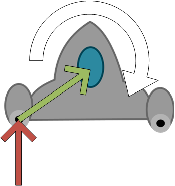
Multiphase Collision Detection

It should be clear that the per-pixel and SAT-based approaches can become very computationally expensive. For this reason, games that need fine-grained collision detection often resort to a multi-phase approach, which utilizes two or more processing passes. Each pass uses an increasingly sophisticated (and therefore costly) collision detection algorithm to find collisions, but only tests those objects that previous passes identified as “possibly colliding”. The more simple methods employed in the first few passes typically can reject a great deal of possible collisions, reducing the number of more expensive comparisons that will be tried later.

The first pass typically consists of testing using axis-aligned bounding boxes or bounding circles, which bound (enclose) the object. As we have already seen, there are very quick collision tests to use with both axis-aligned bounding boxes and with circles. And pair of objects whose bounding areas register a collision are placed in a queue (as a pair) for testing in the next pass.

The next pass will typically resort to a SAT-based algorithm using a simplified outline of the shape in question. This may be the final pass, or it may be used to identify shapes for per-pixel collision detection (or the second pass may be per-pixel detection).

In games that use hierarchical sprite representations (where a sprite may be composed of sub-sprites), the first pass is a bounding area for the entire sprite, but the second pass compares individual parts (often bounding areas for each subpart), which can then be further refined by a SAT or per-pixel approach.

Summary

In this chapter we looked at implementing collision detection using bounding shapes, the separating axis theorem, and per-pixel evaluation. We discussed the merits of the different approaches, and saw how multiphase collision detection can avoid expensive collision detection tests.

There are other techniques we can use to avoid unneeded collision tests as well. We’ll talk about one of these, spatial partitioning in an upcoming chapter.

Audio

Chapter 5

Audio

Get your games rocking!

Subsections of Audio

Introduction

We often focus on the visual aspects of games, but the audio aspects can really make a game shine. Consider that many game tracks are now presented as orchestral performances:

And how important sound effects can be for conveying what is happening in a game?

In this chapter, we will explore both sound effects and music, and how to implement them within MonoGame.

Sound Effects

From the “bing” of a coin box in Super Mario Bros to the reveal chimes of the Zelda series, sound effects provide a powerful mechanism for informing the player of what is happening in your game world.

SoundEffect Class

MonoGame represents sound effects with the SoundEffect class. Like other asset types, we don’t normally construct this directly, we rather load it through the content pipeline. Usually, a sound effect will start as a .wav file, though a handful of other file formats are acceptable.

Once loaded, the SoundEffect can be played with the SoundEffect.Play() method. This is essentially a fire-and-forget method - you invoke, it and the framework takes care of loading and playing the sound.

You can also use the SoundEffect.Play(float volume, float pitch, float pan) to customize the playback:

  • volume ranges from $ 0.0 $ (silence) to $ 1.0 $ (full volume)
  • pitch adjusts the pitch from $ -1.0 $ (down an octave) to $ 1.0 $ (up an octave), with $ 0.0 $ indicating no change
  • pan pans the sound in stereo, with $ -1.0 $ entirely on the left speaker, and $ 1.0 $ on the right, and $ 0.0 $ centered.

Note that the per-sound-effect volume is multiplied by the static SoundEffect.MasterVolume property. This allows for the adjustment of all sound effects in the game, separate from music.

Warning

Note that if you invoke Play() on a sound effect multiple frames in a row, it will start playing another copy of the sound effect on each frame. The result will be an ugly mash of sound. So be sure that you only invoke Play() once per each time you want to use the sound!

SoundEffectInstance Class

If you need finer control of your sound effects, you can also create a SoundEffectInstance from one with: SoundEffect.CreateInstance(). This represents a single instance of a sound effect, so invoking its Play() method will restart the sound from the beginning (essentially, SoundEffect.Play() creates a SoundEffectInstance that plays and disposes of itself automatically).

The SoundEffectInstance exposes properties that can be used to modify its behavior:

  • IsLooped is a boolean that when set to true, causes the sound effect to loop indefinitely.
  • Pan pans the sound in stereo, with $ -1.0 $ entirely on the left speaker, and $ 1.0 $ on the right, and $ 0.0 $ centered.
  • Pitch adjusts the pitch from $ -1.0 $ (down an octave) to $ 1.0 $ (up an octave), with $ 0.0 $ indicating no change
  • Volume ranges from $ 0.0 $ (silence) to $ 1.0 $ (full volume)
  • State returns a SoundState enumeration value, one of (SoundState.Paused, SoundState.Playing, or SoundState.Stopped)

The SoundEffectInstance also provides a number of methods:

  • Play() plays or resumes the sound effect
  • Pause() pauses the sound effect
  • Resume() resumes a paused sound effect
  • Stop() immediately stops the sound effect (so when started it starts from the beginning)
  • Stop(bool immediate) also stops the sound effect, immediately if true, or its authored release phase, i.e. a fade, if false

Perhaps the strongest reason for creating a SoundEffectInstance is to be able to crate positional sound. We’ll discuss this next.

Positional Sounds

Positional sounds provide the illusion of depth and movement by using panning, doppler shift, and other techniques to emulate the affect movement and distance have on sounds. Positional sounds can convey important information in games, especially when combined with surround-sound speakers and headphones.

To create positional sound effects, we need to place the sound in a 3D (or pseudo 2D) soundscape, which incorporates both a listener (i.e. the player) and an emitter (the source of the sound). Consider the example soundscape below:

An example soundscape An example soundscape

We have two sound effects, one played by emitter A and one by emitter B, and the player is represented by the listener. If we imagine the listener is facing downwards, we would expect that the sound from emitter A will play more on the right speaker, and emitter B on the left (given stereo speakers). For a surround sound system, these would be further distinguished by playing on the front speakers.

In addition to determining which speaker(s) a sound is played with, positional sounds also usually incorporate attenuation and doppler effect.

Attenuation in this context means that sound waves get softer the farther they travel (as some of the energy in the wave is absorbed by the air as heat). Thus, as emitter B is farther from the listener than emitter A, we would expect that if the same sound were played by both emitters, emitter B would be softer.

Doppler effect refers to the change in pitch of a sound when either the emitter or listener is moving. When the distance between the emitter and listener is getting smaller, the sound waves emitted by the emitter are closer together (higher frequency), resulting in a higher pitch. And when they are moving apart, the waves are farther apart, resulting in a lower frequency and pitch.

Info

Position, attenuation, and doppler effect represent some of the easiest-to-implement aspects of the physics of sound, which is why they are commonly implemented in video game audio libraries. More complex is the interaction of sound with the environment, i.e. absorption and reflection by surfaces in the game world. This parallels the early days of 3D rendering, when the Phong illumination model (which we’ll talk about soon) provided a simplistic but adequate technique for handling lights in a 3D scene.

The MonoGame framework provides two classes for establishing positional sound, the AudioEmitter and AudioListener.

AudioListener Class

The AudioListener class represents the player (or microphone) in the game world, and all position, attenuation, and doppler effects are calculated relative to its position, orientation, and velocity. It exposes four properties:

  • Position is a Vector3 defining the position of the listener in the game world
  • Forward is a Vector3 defining the direction the listener is facing in the game world.
  • Up is a Vector3 defining the direction up relative to the direction the player is facing (generally it would be Vector3.Up). It is used as part of the 3D math calculating the effects.
  • Velocity is a Vector3 defining the velocity at which the listener is moving in the game world.

When using an AudioListener instance, you would set these each update to reflect the corresponding position, orientation, and velocity of the player.

AudioEmitter Class

The AudioEmitter class represents the source of a sound in the game world. It exposes the same properties as the AudioListener:

  • Position is a Vector3 defining the position of the emitter in the game world
  • Forward is a Vector3 defining the direction the emitter is facing in the game world.
  • Up is a Vector3 defining the direction up relative to the direction the emitter is facing (generally it would be Vector3.Up). It is used as part of the 3D math calculating the effects.
  • Velocity is a Vector3 defining the velocity at which the emitter is moving in the game world.

Playing Positional Sound

Positional sounds are played by a SoundEffectInstance, not by the actual emitter; the emitter rather serves to locate the sound source. Thus, to calculate and apply the 3D effects on a sound effect we would use something like:

SoundEffect sfx = Content.Load<sfx>("sound");
var instance = sfx.CreateInstance();
var listener = new AudioListener();
// TODO: Position and orient listener 
var emitter = new AudioEmitter();
// TODO: Position and orient emitter
instance.Apply3D(listener, emitter);

Using Positional Sound in a 2D Game

The positional sound support in MonoGame is for 3D soundscapes, but just as we can render 2D sprites using 3D hardware, we can create 2D soundscapes in 3D. The easiest technique for this is to position all our emitters and listeners in the plane $ z=0 $.

The Vector3 constructor actually has support for this built-in as it can take a Vector2 for the X and Y components, and a separate scalar for the Z component. Consider a game where we represent the player’s position with a Vector2 position, direction with a Vector2 direction, and velocity with a Vector2 velocity. We can update our AudioListener listener with:

// Update listener properties
listener.Position = new Vector3(position, 0);
listener.Forward = new Vector3(direction, 0);
listener.Velocity = new Vector3(velocity, 0);

Since the Up vector will never change, we can just set it to Vector3.UnitZ (which is the vector $ <0,0,1> $) when we first create the listener.

The emitters would be set up the same way.

Music

Music also has a powerful role to play in setting the mood. It can also be used to convey information to the player, as Super Mario Bros does when the remaining time to finish the level falls below 1 minute.

Song Class

While it is possible to play music using a SoundEffect, MonoGame supports music through the Song class. This represents a song loaded from a wav or mp4 file.

In addition to the audio data, the Song defines properties for accessing the audio file’s metadata:

  • Name is the name of the song
  • Album is the album the song is from
  • Artist is the song’s artist
  • Duration is the length of the song.
  • Genre is the genre of the song
  • TrackNumber is song’s track number on its album

Note that for these properties to be populated, the original audio file would need to have the corresponding metadata set.

Unlike the SoundEffect, the Song class does not have a play method. Instead it is played with the static MediaPlayer class, i.e.:

Song song = Content.Load<Song>("mysong");
MediaPlayer.Play(song);

SongCollection Class

Invoking MediaPlayer.Play() will immediately end the current song, so if you want your game to transition between songs smoothly, you’ll probably want to use the SongCollection class.

As you might expect, this is a collection of Song objects, and implements methods:

  • Add(Song song) adds a song to the collection
  • Clear() clears the collection.

SongCollections can also be played with the static MediaPlayer.Play(SongCollection collection) method:

Song song1 = Content.Load<Song>("song1");
Song song2 = Content.Load<Song>("song2");
Song song3 = Content.Load<Song>("song3");
SongCollection songCollection = new SongCollection();
songCollection.Add(song1);
songCollection.Add(song2);
songCollection.Add(song3);
MediaPlayer.Play(songCollection);

The MediaPlayer Class

The static MediaPlayer class is really an interface to the Windows Media Player. Unlike the SoundEffect class, which communicates directly with the sound card and manipulates audio buffers, songs are piped through the Windows Media Player. Hence, the reason MediaPlayer can only play a single song at a time.

Some of the most useful properties of the MediaPlayer for games are:

  • IsMuted - A boolean property that can be used to mute or unmute the game’s music
  • Volume - A number between 0 (silent) and 1 (full volume) that the music will play at
  • IsRepeating - A boolean property that determines if the song or song list should repeat
  • IsShuffled - A boolean property that determines if a song list should be played in a shuffled order
  • State - A value of the MediaState enum, describing the current state of the media player, which can be MediaState.Paused, MediaState.Playing, or MediaState.Stopped.

Much like you would expect from a media playing device, the MediaPlayer also implements some familiar controls as methods:

  • Play(Song song) and Play(SongList songList) play the specified song or song list.
  • Pause() pauses the currently playing song
  • Resume() resumes a paused song
  • Stop() stops playing the current song
  • MoveNext() moves to the next song in the song list
  • MovePrevious() moves to the previous song in the song list

In addition, the MediaPlayer implements two events that may be useful:

  • ActiveSongChanged - triggered when the active song changes
  • MediaStateChanged - triggered when the media state changes
Info

This section only touches on the classes, methods and properties of the Microsoft.Xna.Framework.Media namespace most commonly used in games. Because it is a wrapper around the Windows Media Player, it is also possible to access and play the users’ songs and playlists that have been added to Windows Media Player. Refer to the MonoGame documentation for more details.

Physics

For every action…

Subsections of Physics

Introduction

Much of gameplay derives from how agents in the game world (players, enemies, puzzle pieces, interactive items, etc) interact with each other. This is the domain of physics, the rules of how physical (or game) objects interact. In a sense the game physics define how the game’s simulation will unfold.

While game physics often correlate to the physics of the world we inhabit they don’t have to! In fact, most game physics approaches at least simplify real-world physics models to allow for real-time processing, and some abandon real-world physics altogether.

When games do try to implement realistic physics, they typically start with rigid body dynamics, a simplification of real-world physics where objects are represented as a rigid body and a point mass. In games, the rigid body is essentially the collision shape we covered in chapter 4, and a point mass represents the object’s position as a vector, and the mass as a float.

In this chapter we’ll examine how to implement rigid body physics in games.

Linear Dynamics

At some point in your K-12 education, you probably encountered the equations of linear motion, which describe motion in terms of time, i.e.:

$$ v = at + v_0 \tag{1} $$ $$ p = p_0 + v_ot + \frac{1}{2}at^2 \tag{2} $$ $$ p = p_0 + \frac{1}{2}(v+v_0)t \tag{3} $$ $$ v^2 = v_0^2 2a(r - r_0) \tag{4} $$ $$ p = p_0 + vt - \frac{1}{2}at^2 \tag{5} $$

These equations can be used to calculate motion in a video game setting as well, i.e. to calculate an updated position vector2 position given velocity vector2 velocity and acceleration vector2 acceleration, we can take equation (5):

position += velocity * gameTime.ElapsedGameTime.TotalSeconds + 1/2 * acceleration * Math.Pow(gameTime.ElapsedGameTime.TotalSeconds);

This seems like a lot of calculations, and it is. If you’ve also taken calculus, you probably encountered the relationship between position, velocity, and acceleration.

position is where the object is located in the world velocity is the rate of change of the position acceleration is the rate of change of the velocity

If we represent the position as a function (6), then velocity is the derivative of that function (7), and the acceleration is the second derivative (8):

$$ s(t) \tag{6} $$ $$ v(t) = s'(t) \tag{7} $$ $$ a(t) = v'(t) \tag{8} $$

So, do we need to do calculus to perform game physics? Well, yes and no.

Calculus is based around the idea of looking at small sections of a function (it literally comes from the latin term for “small stone”). Differential calculus cuts a function curve into small pieces to see how it changes, and Integral calculus joins small pieces to see how much there is.

Now consider our timestep - 1/30th or 1/60th of a second. That’s already a pretty small piece. So if we want to know the current velocity, given our acceleration, we could just look at that small piece, i.e.:

velocity += acceleration * gameTime.elapsedGameTime.TotalSeconds;

Similarly, our position is:

position += velocity * gameTime.elapsedGameTime.TotalSeconds

That’s it. We can consider our acceleration as an instantaneous change (i.e. we apply a force). Remeber the definition of force?

$$ \overline{F} = m\overline{a} \tag{9} $$

So to find our acceleration, we rearrange equation 9 to read:

$$ \overline{a} = \overline{F}/m $$

Thus, our acceleration would be the force acting on the body, divided by the mass of the body. We could calculate this from real values, or try different numbers until we found ones that “felt right”.

If we have multiple forces acting on an object, we simply sum the individual accelerations to find the net acceleration at that instant, which is then applied to the velocity.

Tip

Games are a “soft” simulation, in that we are emulating, but often not duplicating behavior of objects the real world. This also brings into play hyperreality, a philosophical concept that deals with modern humans’ inability to distinguish perceptions of reality and simulated realities.

One great example is LucasArt’s Digital Molecular Matter developed for the Force Unleashed series. Early tests with the physics engine duplicated the breaking of objects based on the actual molecular physics involved. Playtesters responded that it “felt fake” as wood did not explode into splinters and glass did not shatter into clouds of thousands of pieces when broken… so the developers made the effects more unrealistically intense to satisfy player expectations.

Lunar Lander

Let’s look at a simple example, a lunar-lander style game. We have a lunar lander that has a downward-facing thruster that the player can fire with the spacebar, causing an acceleration of 10 pixels/second2. The lander is also moving laterally at a velocity of 100 pixels/second, and gravity is pulling downward at 5 pixels/second2. We could write an update function like:

// Initial velocity 
Vector2 velocity = new Vector2(10, 0);

public void Update(GameTime gameTime) 
{
    float t = (float)gameTime.ElapsedGameTime.TotalSeconds;
    if(keyboardState.IsKeyDown(Keys.Space))
    {
        // apply thruster acceleration upward
        velocity += new Vector2(0, -40) * t;
    }
    // apply gravity downward
    velocity += new Vector2(0,30) * t
    // update position
    position += velocity * t;
}

Note that we can avoid all those complicated calculations, because we are only looking at a small slice of time. If we wanted to look at a bigger span of time, i.e. where a bomb might fall, we have to take more into account.

Also, notice that for this game, we ignore any friction effects (after all, we’re in the vacuum of space). Game programmers often take advantage of any simplifications to these calculations we can.

Angular Dynamics

There is a second set of equations that govern angular motion (rotation) you may have encountered, where $ \omega $ is angular velocity, $ \alpha $ the angular acceleration, and $ \theta $ the rotation of the body:

$$ \omega = \omega_0 + \alpha t \tag{1} $$ $$ \theta = \theta_0 + \omega_0 t + \frac{1}{2}\alpha t^2 \tag{2} $$ $$ \theta = \theta_0 + \frac{1}{2}(\omega_0 + \omega)t \tag{3} $$ $$ \omega^2 = \omega_0^2 + 2\alpha(\theta-\theta_0) \tag{4} $$ $$ \theta = \theta_0 + \omega t - \frac{1}{2}\alpha t^2 \tag{5} $$

These equations parallel those we saw for linear dynamics, and in fact, have the same derivative relationships between them:

$$ \theta(t) \tag{6} $$ $$ \omega(t) = \theta'(t) \tag{7} $$ $$ \alpha(t) = \omega'(t) \tag{8} $$

And, just like linear dynamics, we can utilize this relationship and our small timestep to sidestep complex calculations in our code. Thus, we can calculate the rotational change from the angular velocity (assuming float rotation, angularVelocity, and angularAcceleration values expressed in radians):

rotation += angularVelocity * gameTime.elapsedGameTime.TotalSeconds;

And the change in angular velocity can be calculated from the angular acceleration:

angularAcceleration = angularVelocity * gameTime.elapsedGameTime.TotalSeconds;

Finally, angular acceleration can be imposed with an instantaneous force. However, this is slightly more complex than we saw with linear dynamics, as this force needs to be applied somewhere other than the center of mass. Doing so applies both rotational and linear motion to an object. This rotational aspect is referred to as torque, and is calculated by taking the cross product of the force’s point of application relative to the center of mass and the force vector. Thus:

$$ \tau = \overline{r} x \overline{F} $$

Where $ tau $ is our torque, $ \overline{r} $ is the vector from the center of mass to where the force is applied, and $ \overline{F} $ is the force vector.

torque = force.X * r.Y - force.Y * r.X;

Torque is the force imposing angular acceleration, and can be applied directly to the velocity:

angularAcceleration += torque * gameTime.ElapsedGameTime.TotalSeconds;

And much like force and linear acceleration, multiple torques applied to an object are summed.

Info

XNA does not define the cross product function in its Vector2 library, so we computed it manually above. If you would like to add it as a method in your projects, we can do so using an extension method, i.e. define in one of your game’s namespaces:

public static class Vector2Extensions {

    /// <summary>
    /// Computes the cross product of two Vector2 structs
    /// </summary>
    /// <param ref="a">The first vector</param>
    /// <param ref="b">The second vector</param>
    public static float CrossProduct(Vector2 a, Vector2 b)
    {
        return a.X * b.Y - a.Y * b.X;
    }

    /// <summary>
    /// Computes the cross product of this vector with another
    /// </summary>
    /// <param ref="other">the other vector</param>
    public static float Cross(this Vector2 a, Vector2 other)
    {
        return CrossProduct(a, other);
    }
}

As long as this class is in scope (i.e. you have an appropriate using statement), you should be able to invoke Cross() on any Vector2. So the code listing:

torque = force.X * r.Y - force.Y * r.X;

Could be rewritten as:

torque = force.Cross(r);


Rocket Thrust

Let’s work through an example. Consider this diagram:

Torque applied to a spaceship Torque applied to a spaceship

The red arrow is the force vector applied from the left rocket. The green arrow is the vector from the position the force is applied to the center of mass of the ship. Firing just this one rocket will impose a rotation on the ship in the direction of the white arrow. Firing both rockets will impose an opposite torque, cancelling both.

Let’s write the control code for this spaceship. We’ll define class fields for both linear and angular velocity and acceleration, as well as position, direction, and angle. We’ll also supply a constant for the amount of linear acceleration applied by our spaceship:

// Constants
float LINEAR_ACCELERATION = 10;

// Linear movement fields
Vector2 position;
Vector2 direction;
Vector2 velocity;

// Angular movement fields
float angle; 
float angularVelocity;

Then we’ll use these in our update method:

public void Update(GameTime gameTime) 
{
    KeyBoardState keyboardState = Keyboard.GetState();
    float t = (float)gameTime.ElapsedGameTime.TotalSeconds;
    Vector2 acceleration = Vector2.Zero; // linear acceleration
    float angularAcceleration = 0; // angular acceleration

    // Determine if the left rocket is firing
    if(keyboardState.IsKeyPressed(Keys.A))
    {
        // LABEL A: Apply linear force in the direction we face from left rocket
        acceleration += direction * LINEAR_ACCELERATION * t;

        // TODO 1: Calculate and apply torque from left rocket
    }

    // Determine if the right rocket is firing 
    if(keyboardState.IsKeyPressed(Keys.D))
    {
        // LABEL B: Apply linear force in the direction we face from right rocket
        acceleration += direction * LINEAR_ACCELERATION * t;

        // TODO 2: Calculate and apply torque from right rocket
    }

    // Update linear velocity and position 
    velocity += acceleration * t;
    position += velocity * t;

    // update angular velocity and rotation 
    angularVelocity += angularAcceleration * t;
    angle += angularVelocity * t;

    // LABEL C: Apply rotation to our direction vector  
    direction = Vector2.Transform(Vector2.UnitY, new Matrix.CreateRotationZ(theta));
}

There’s a lot going on in this method, so let’s break it down in pieces, starting with the code following the LABEL comments:

LABEL A & B - Apply linear force in the direction we face from left rocket and right rocket

When we apply force against a body not toward its center, part of that force becomes torque, but the rest of it is linear acceleration. Technically, we can calculate exactly what this is with trigonometry. But in this case, we don’t care - we just want the ship to accelerate in the direction it is facing. So we multiply the direction vector by a constant representing the force divided by the mass of our spaceship (acceleration), and the number of seconds that force was applied.

Note that we consider our spaceship mass to be constant here. If we were really trying to be 100% accurate, the mass would change over time as we burn fuel. But that’s extra calculations, so unless you are going for realism, it’s simpler to provide a constant, a lá LINEAR_ACCELERATION. Yet another example of simplifying physics for games.

LABEL C - Apply rotation to our direction vector

We need to know the direction the ship is facing to apply our linear acceleration. Thus, we need to convert our angle angle into a Vector2. We can do this with trigonometry:

direction.X = (float)Math.Cos(theta);
direction.Y = (float)Math.Sin(theta);

Or we can utilize matrix operations:

direction = Vector2.Transform(Vector2.UnitY, new Matrix.CreateRotationZ(theta));

We’ll discuss the math behind this second method soon. Either method will work.

TODO 1: Calculate and apply torque from left rocket

Here we need to insert code for calculating the torque. First, we need to know the distance from the rocket engine to the center of mass of the ship. Let’s assume our ship sprite is $ 152x115 $, and our center of mass is at $ <76,50> $. Thus, our r vector would be:

Vector2 r = new Vector2(76,50);

The second value we need is our force. We could factor in our ship rotation at this point, but it is easier if we instead rotate our coordinate system and place its origin at the center of mass for the ship, i.e.:

The rotated coordinate system The rotated coordinate system

Then our force vector is simply a vector in the upward direction, whose magnitude is the amount of the force tangential to the r vector. For simplicity, we’ll use a literal constant instead of calculating this:

Vector2 force = new Vector2(0, FORCE_MAGNITUDE);

Then we can calculate the torque with the cross product of these two vectors:

float torque = force.X * r.Y - force.Y * r.X;

And then calculate the rotational acceleration:

float angularAcceleration += torque / ROTATIONAL_INERTIA;

The ROTATIONAL_INERTIA represents the resistance of the body to rotation (basically, it plays the same role as mass in linear dynamics). For simplicity, we could treat it as $ 1 $ (no real effect - after all, we’re in a vacuum), which allows us to refactor as:

float angularAcceleration += torque;

TODO 2: Calculate and apply torque from right rocket

Now that we’ve seen the longhand way of doing things “properly”, let’s apply some game-programming savvy shortcuts to our right-engine calculations.

Note that for this example, the vector r does not change - the engine should always be the same distance from the center of mass, and the force vector of the engine will always be in the same direction. relative to r. So the cross product of the two will always be the same. So we could pre-calculate this value, and apply the proper moment of inertia, leaving us with a single constant representing the angular acceleration from the engines which we can represent as a constant, ANGULAR_ACCELERATION. Since this is reversed for the right engine, our simplified acceleration calculation would be:

angularAcceleration -= ANGULAR_ACCELERATION * t;

(and the right engine would have been angularAcceleration += ANGULAR_ACCELERATION * t;)

Thus, with careful thought we can simplify six addition operations, four multiplications, one subtraction, one multiplication, and two struct allocation operations to just two multiplications and two additions. This kind of simplification and optimization is common in game programming. And, in fact, after calculating the ANGULAR_ACCELERATION value we would probably tweak it until the movement felt natural and fun (or just guess at the value to begin with)!

Of course, if we were doing scientific simulation, we would instead have to carry out all of the calculations, couldn’t use fudge factors, and would have additional considerations. For example, if the fuel tanks are not at the center of mass, then every time we fire our rockets the center of mass will shift! That is why scientific simulations are considered hard simulations. Not so much because they are hard to write - but because accuracy is so important.

Elastic Collisions

Now that we’ve looked at movement derived from both linear and angular dynamics, let’s revisit them from the perspective of collisions. If we have two rigid bodies that collide, what should be the outcome? Consider an elastic collision (one in which the two objects “bounce off” one another). From Newtonian mechanics we know that:

  1. Energy must be conserved
  2. Momentum must be conserved

Thus, if we consider our two objects in isolation (as a system of two), the total system must have the same energy and momentum after the collision that it had before (Note we are talking about perfectly elastic collisions here - in the real world some energy would be converted to heat and sound).

Momentum is the product of mass and velocity of an object:

$$ \rho = mv\tag{0} $$

Since we have two objects, the total momentum in the system is the sum of those:

$$ \rho = m_1v_1 + m_2v_2\tag{1} $$

And, due to the law of conservation of momentum,

$$ \rho_{before} = \rho_{after} \tag{2} $$

So, substituting equation 1 before and after the collision we find:

$$ m_1u_1 + m_2u_2 = m_1v_1 + m_2v_2\tag{3} $$

Where $ u $ is the velocity before a collision, and $ v $ is the velocity after (note that the mass of each object does not change).

And since our objects are both moving, they also have kinetic energy:

$$ E_k = \frac{1}{2}mv^2\tag{4} $$

As energy is conserved, the energy before the collision and after must likewise be conserved:

$$ E_{before} = E_{after} \tag{5} $$

Substituting equation 4 into 5 yields:

$$ \frac{1}{2}m_0u_0^2 + \frac{1}{2}m_1u_1^2 = \frac{1}{2}m_0v_0^2 + \frac{1}{2}m_1v_1^2 \tag{6} $$

Assuming we enter the collision knowing the values of $ u_0, u_1, m_0, and m_1 $, we have two unknowns $ v_0 $ and $ v_1 $ and two equations containing them (equations 3 and 6). Thus, we can solve for $ v_0 $ and $ v_1 $:

$$ v_0 = \frac{m_0 - m_1}{m_0 + m_1}u_0 + \frac{2m_1}{m_0+m_1}u_1 \tag{7} $$ $$ v_1 = \frac{2m_0}{m_0+m_1}u_0 + \frac{m_1 - m_0}{m_0 + m_1}u_1 \tag{8} $$

These two equations can give us the new velocities in a single dimension. But we’re primarily interested in two dimensions, and our velocities are expressed as Vector2 objects. However, there is a simple solution; use a coordinate system that aligns with the axis of collision, i.e. for two masses colliding, A and B:

Aligning the coordinate system with the axis of collision Aligning the coordinate system with the axis of collision

Note how the X-axis in the diagram is aligned with the line between the centers of mass A and B. We can accomplish this in code by calculating the vector between the center of the two bodies, and determining the angle between that vector and the x-Axis:

Finding the angle between the line of collision and x-axis Finding the angle between the line of collision and x-axis

Remember that the angle between two vectors is related to the dot product:

$$ cos\theta = \frac{ a \cdotp b}{||a||*||b||} \tag {9} $$

If both vectors $ a $ and $ b $ are of unit length (normalized), then this simplifies to:

$$ cos\theta = a \cdotp b \tag {10} $$

And $ \theta $ can be solved for by:

$$ \theta = cos^{-1}(a \cdotp b) \tag{11} $$

Given two rigid bodies A and B, we could then calculate this angle using their centers:

// Determine the line between centers of colliding objects A and B
Vector2 collisionLine = A.Center - B.Center;
// Normalize that line
collisionLine.Normalize();
// Determine the angle between the collision line and the x-axis
float angle = Math.Acos(Vector2.Dot(collisionLine, Vector2.UnitX));

Once we have this angle, we can rotate our velocity vectors using it, so that the coordinate system now aligns with that axis:

Vector2 u0 = Vector2.Transform(Matrix.CreateRotationZ(A.Velocity, angle));
Vector2 u1 = Vector2.Transform(Matrix.CreateRotationZ(B.Velocity, angle));

We can use these values, along with the masses of the two objects, to calculate the changes in the X-component of the velocity using equations (7) and (8):

float m0 = A.Mass;
float m1 = B.Mass;
Vector2 v0;
v0.X = ((m0 - m1) / (m0 + m1)) * u0.X + ((2 * m1) / (m0 + m1)) * u1.X;
Vector2 v1;
v1.X = ((2 * m0) / (m0 + m1)) * u0.X + ((m1 - m0) / (m0 + m1)) * u1.X;

And, because the collision axis and the x-axis are the same, this transfer of velocity only occurs along the x-axis. The y components stay the same!

v0.Y = u0.Y;
v1.Y = u0.Y;

Then, we can rotate the velocities back to the original coordinate system and assign the transformed velocities to our bodies:

A.Velocity = Vector2.Transform(v0, Matrix.CreateRotationZ(-angle));
B.Velocity = Vector2.Transform(v1, Matrix.CreateRotationZ(-angle));

Some notes on this process:

  1. at this point we are not accounting for when the collision has gone some way into the bodies; it is possible that after velocity is transferred one will be “stuck” inside the other. A common approach to avoid this is to move the two apart based on how much overlap there is. A more accurate and costly approach is to calculate the time from the moment of impact until end of frame, move the bodies with the inverse of their original velocities multiplied by this delta t, and then apply the new velocities for the same delta t.

  2. this approach only works on two bodies at a time. If you have three or more colliding, the common approach is to solve for each pair in the collision multiple times until they are not colliding. This is not accurate, but gives a reasonable approximation in many cases.

Physics Engines

If we want to incorporate more robust and realistic physics than that we have just explored, we would be well-served to look at physics engines designed for use in games. These are simulations built along the same lines as what we’ve discussed - essentially they represent the objects in the game world as rigid bodies, and provide the means for simulating them somewhat realistically.

Farseer / Velcro Physics

One of the best-known of the physics engines developed for XNA was the Farseer Physics Engine, which was renamed to Velcro Physics when it was moved from CodePlex to GitHub.

Game Architecture

Reorganizing your code…

Subsections of Game Architecture

Introduction

Now that you’ve moved through much of the foundations of building games, let’s take a step back and talk about how to best organize that task. After all, games are one of the most complex software systems you can build. In the words of Jason Gregory, a game is:

A soft real-time interactive agent-based simulation

This means that not only do you need to process user input, update a simulated world, and then render that simulated world, you also have to do this in realtime (i.e. within 1/60th of a second)! This is not a trivial challenge!

As with any software system, organization can go a long way to managing this complexity. Consider this diagram of a AAA game engine’s software architecture:

Software Engine Architecture Software Engine Architecture

Note how the engine is broken into systems and organized into layers. Building an engine like this is outside the scope of this book (I encourage you to read Jason Gregory’s Game Engine Architecture if you’d like to delve into it), but the idea of loosely coupled systems is certainly something we can adapt. Moreover, it is already explicitly supported by the MonoGame framework. We’ll explore how in this chapter.

Game Services

A common approach in software architecture for loose coupling of systems is the use of services. Services are implemented with 1) a service provider - essentially a collection of services that can be searched for a service, and new services can be registered with, 2) interfaces that define specific services how to work with the service, and 3) classes that implement these interfaces. This is the Service Locator Pattern as implemented in C#.

For a Service Provider, MonoGame provides the GameServiceContainer class, and the Game class has one as its Service property. The default game class adds at least two services: an IGraphicsDeviceService and an IGraphicsDeviceManager. If we need to retrieve the graphics device for some reason we could use the code:

var gds = game.Services.GetService(typeof(IGraphicDeviceService));
GraphicsDevice gd = gds.GraphicsDevice;

We can add any service we want to with the GameServicesContainer.AddService(Type type, object provider). In effect, the GameServicesContainer acts as a dictionary for finding initialized instances of services you would use across the game. For example, we might want to have a custom service for reporting achievements in the game. Because the implementation would be different for the Xbox than the Playstation, we could define an interface to represent our type:

public class IAchievementService 
{
    public void RegisterAchievement(Achievement achievement);
}

Then we could author two classes implementing this interface, one for the Xbox and one for the Playstation. We would initalize and register the appropriate one for the build of our program:

game.Services.AddService(IAchievementService, new XBoxAchievementService());

This provides us with that desirable “loose coupling”, where the only change we’d need to make between the two builds is what achievement service we initialize. A second common use for the GameServicesContainer is it can be passed to a constructor to provide multiple services as a single parameter, instead of having to pass each one separately. It can also be held onto to retrieve the service at a later point in the execution, as is the case with the ContentManager constructor.

Game services are a good replacement for systems that you might otherwise use the Singleton Pattern to implement.

Game Components

A second useful decoupling pattern in MonoGame is the use of game components. You’ve probably noticed that many of the classes you have written have a similar pattern: they each have a LoadContent(), Update(), and Draw() method, and these often take the same arguments. In your game class, you probably mostly invoke these methods for each class in turn. MonoGame provides the concept of game components to help manage this task. This involves: 1) a GameComponentCollection which game components are registered with, and components are implemented by extending the GameComponent or DrawableGameComponent base classes.

The Game implements a GameCollection in its Components property. It will iterate through all components it holds, invoking the Update() and Draw() methods within the game loop.

GameComponent

The GameComponent base class implements IGameComponent, IUpdatable, and IDisposable interfaces. It has the following properties:

  • Enabled - this boolean indicates if the component will be updated
  • Game - the game this component belongs to
  • UpdateOrder - an integer used to sort the order in which game component’s Update() method is invoked

It also has the following virtual methods, which can be overridden:

  • Dispose(bool disposing) - Disposes of the component
  • Initialize() - Initializes the component; used to set/load any non-graphical content; invoked during the game’s initialization step
  • Update(GameTime gameTime) - Invoked every pass through the game loop

Finally, it also implements the following events:

  • EnabledChanged - triggered when the Enabled property changes
  • UpdateOrderChanged - triggered when the UpdateOrder property changes

DrawableGameComponent

The DrawableGameComponent inherits from the GameComponent base class, and additionally implements the IDrawable interface. In addition to its inherited properties, it declares:

  • DrawOrder - an integer that determines the order game components are drawn in
  • GraphicsDevice - the graphics device used to draw the game component
  • Visible - a boolean that determines if the game component should be drawn

It also has the additional virtual methods:

  • LoadContent() - Loads graphical content, invoked by the game during its content loading step
  • Draw(GameTime gameTime) - Draws the game component, invoked during the game loop

Finally, it implements the additional properties:

  • DrawOrderChanged - triggered when the DrawOrder property changes
  • VisibleChanged - triggered when the Visible property changes
Info

The concept of Game Component espoused by MonoGame is not the same one defined by the Component Pattern, though it could potentially be leveraged to implement that pattern.

Game Screens

XNA offered a sample building with these ideas that further organized a game into screens that has been ported to MonoGame.This was heavily influenced by Windows Phone, and includes gestures and “tombstoning” support. A more simplified form is presented here. It organizes a game into “screens”, each with its own logic and rendering, such as a menu, puzzle, cutscene, etc.

A scene manager game component manages a stack of these screens, and updates and renders the topmost. Thus, from a gameplay screen, if we trigger a cutscene it would be pushed onto the stack, play, and then pop itself from the stack. Similarly, pressing the “menu” button would push the menu screen onto the stack, leaving the player to interact with the menu instead of the game. Screens manage their transition on and off this stack - and can incorporate visual effects into the transition.

ScreenState Enum

This enumeration represents the states a GameScreen can be in.

/// <summary>
/// Enumerations of the possible screen states
/// </summary>
public enum ScreenState
{
    TransitionOn,
    Active,
    TransitionOff,
    Hidden
}

GameScreen

The GameScreen class is an abstract base class that represents a single screen.

/// <summary>
/// A screen is a single layer of game content that has
/// its own update and draw logic and can be combined 
/// with other layers to create complex menus or game
/// experiences
/// </summary>
public abstract class GameScreen
{
    /// <summary>
    /// Indicates if this screen is a popup
    /// </summary>
    /// <remarks>
    /// Normally when a new screen is brought over another, 
    /// the covered screen will transition off.  However, this
    /// bool indicates the covering screen is only a popup, and 
    /// the covered screen will remain partially visible
    /// </remarks>
    public bool IsPopup { get; protected set; }

    /// <summary>
    /// The amount of time taken for this screen to transition on
    /// </summary>
    protected TimeSpan TransitionOnTime {get; set;} = TimeSpan.Zero;

    /// <summary>
    /// The amount of time taken for this screen to transition off
    /// </summary>
    protected TimeSpan TransitionOffTime {get; set;} = TimeSpan.Zero;

    /// <summary>
    /// The screen's position in the transition
    /// </summary>
    /// <value>Ranges from 0 to 1 (fully on to fully off)</value>
    protected float TransitionPosition { get; set; } = 1;

    /// <summary>
    /// The alpha value based on the current transition position
    /// </summary>
    public float TransitionAlpha => 1f - TransitionPosition;

    /// <summary>
    /// The current state of the screen
    /// </summary>
    public ScreenState ScreenState { get; set; } = ScreenState.TransitionOn;

    /// <summary>
    /// Indicates the screen is exiting for good (not simply obscured)
    /// </summary>
    /// <remarks>
    /// There are two possible reasons why a screen might be transitioning
    /// off. It could be temporarily going away to make room for another
    /// screen that is on top of it, or it could be going away for good.
    /// This property indicates whether the screen is exiting for real:
    /// if set, the screen will automatically remove itself as soon as the
    /// transition finishes.
    /// </remarks>
    public bool IsExiting { get; protected internal set; }
    
    /// <summary>
    /// Indicates if this screen is active
    /// </summary>
    public bool IsActive => !_otherScreenHasFocus && (
        ScreenState == ScreenState.TransitionOn ||
        ScreenState == ScreenState.Active);

    private bool _otherScreenHasFocus;

    /// <summary>
    /// The ScreenManager in charge of this screen
    /// </summary>
    public ScreenManager ScreenManager { get; internal set; }

    /// <summary>
    /// Gets the index of the player who is currently controlling this screen,
    /// or null if it is accepting input from any player. 
    /// </summary>
    /// <remarks>
    /// This is used to lock the game to a specific player profile. The main menu 
    /// responds to input from any connected gamepad, but whichever player makes 
    /// a selection from this menu is given control over all subsequent screens, 
    /// so other gamepads are inactive until the controlling player returns to the 
    /// main menu.
    /// </remarks>
    public PlayerIndex? ControllingPlayer { protected get; set; }

    /// <summary>
    /// Activates the screen.  Called when the screen is added to the screen manager 
    /// or the game returns from being paused.
    /// </summary>
    public virtual void Activate() { }

    /// <summary>
    /// Deactivates the screen.  Called when the screen is removed from the screen manager 
    /// or when the game is paused.
    /// </summary>
    public virtual void Deactivate() { }

    /// <summary>
    /// Unloads content for the screen. Called when the screen is removed from the screen manager
    /// </summary>
    public virtual void Unload() { }

    /// <summary>
    /// Updates the screen. Unlike HandleInput, this method is called regardless of whether the screen
    /// is active, hidden, or in the middle of a transition.
    /// </summary>
    public virtual void Update(GameTime gameTime, bool otherScreenHasFocus, bool coveredByOtherScreen)
    {
        _otherScreenHasFocus = otherScreenHasFocus;

        if (IsExiting)
        {
            // If the screen is going away forever, it should transition off
            ScreenState = ScreenState.TransitionOff;

            if (!UpdateTransitionPosition(gameTime, TransitionOffTime, 1))
                ScreenManager.RemoveScreen(this);
        }
        else if(coveredByOtherScreen)
        {
            // if the screen is covered by another, it should transition off
            ScreenState = UpdateTransitionPosition(gameTime, TransitionOffTime, 1)
                ? ScreenState.TransitionOff
                : ScreenState.Hidden;
        }
        else
        {
            // Otherwise the screen should transition on and become active.
            ScreenState = UpdateTransitionPosition(gameTime, TransitionOnTime, -1)
                ? ScreenState.TransitionOn
                : ScreenState.Active;
        }
    }

    /// <summary>
    /// Updates the TransitionPosition property based on the time
    /// </summary>
    /// <param name="gameTime">an object representing time in the game</param>
    /// <param name="time">The amount of time the transition should take</param>
    /// <param name="direction">The direction of the transition</param>
    /// <returns>true if still transitioning, false if the transition is done</returns>
    private bool UpdateTransitionPosition(GameTime gameTime, TimeSpan time, int direction)
    {
        // How much should we move by?
        float transitionDelta = (time == TimeSpan.Zero)
            ? 1
            : (float)(gameTime.ElapsedGameTime.TotalMilliseconds / time.TotalMilliseconds);

        // Update the transition time
        TransitionPosition += transitionDelta * direction;

        // Did we reach the end of the transition?
        if(direction < 0 && TransitionPosition <= 0 || direction > 0 && TransitionPosition >= 0)
        {
            TransitionPosition = MathHelper.Clamp(TransitionPosition, 0, 1);
            return false;
        }

        // if not, we are still transitioning
        return true;
    }

    /// <summary>
    /// Handles input for this screen.  Only called when the screen is active,
    /// and not when another screen has taken focus.
    /// </summary>
    /// <param name="gameTime">An object representing time in the game</param>
    /// <param name="input">An object representing input</param>
    public virtual void HandleInput(GameTime gameTime, InputState input) { }

    /// <summary>
    /// Draws the GameScreen.  Only called with the screen is active, and not 
    /// when another screen has taken the focus.
    /// </summary>
    /// <param name="gameTime">An object representing time in the game</param>
    public virtual void Draw(GameTime gameTime) { }

    /// <summary>
    /// This method tells the screen to exit, allowing it time to transition off
    /// </summary>
    public void ExitScreen()
    {
        if (TransitionOffTime == TimeSpan.Zero)
            ScreenManager.RemoveScreen(this);    // If the screen has a zero transition time, remove it immediately
        else
            IsExiting = true;    // Otherwise flag that it should transition off and then exit.
    }
}

ScreenManager

The ScreenManager class manages the screens, updating and drawing only when appropriate.

/// <summary>
/// The ScreenManager is a component which manages one or more GameScreen instance.
/// It maintains a stack of screens, calls their Update and Draw methods when 
/// appropriate, and automatically routes input to the topmost screen.
/// </summary>
public class ScreenManager : DrawableGameComponent
{
    private readonly List<GameScreen> _screens = new List<GameScreen>();
    private readonly List<GameScreen> _tmpScreensList = new List<GameScreen>();

    private readonly ContentManager _content;
    private readonly InputState _input = new InputState();

    private bool _isInitialized;

    /// <summary>
    /// A SpriteBatch shared by all GameScreens
    /// </summary>
    public SpriteBatch SpriteBatch { get; private set; }

    /// <summary>
    /// A SpriteFont shared by all GameScreens
    /// </summary>
    public SpriteFont MenuFont { get; private set; }

    /// <summary>
    /// Constructs a new ScreenManager
    /// </summary>
    /// <param name="game">The game this ScreenManager belongs to</param>
    public ScreenManager(Game game) : base(game) 
    {
        _content = new ContentManager(game.Services, "Content");
    }

    /// <summary>
    /// Initializes the ScreenManager
    /// </summary>
    public override void Initialize()
    {
        base.Initialize();
        _isInitialized = true;
    }

    /// <summary>
    /// Loads content for the ScreenManager and its screens
    /// </summary>
    protected override void LoadContent()
    {
        SpriteBatch = new SpriteBatch(GraphicsDevice);
        MenuFont = _content.Load<SpriteFont>("MenuFont");

        // Tell each of the screens to load thier content 
        foreach(var screen in _screens)
        {
            screen.Activate();
        }
    }

    /// <summary>
    /// Unloads content for the ScreenManager's screens
    /// </summary>
    protected override void UnloadContent()
    {
        foreach(var screen in _screens)
        {
            screen.Unload();
        }
    }

    /// <summary>
    /// Updates all screens managed by the ScreenManager
    /// </summary>
    /// <param name="gameTime">An object representing time in the game</param>
    public override void Update(GameTime gameTime)
    {
        // Read in the keyboard and gamepad
        _input.Update();

        // Make a copy of the screen list, to avoid confusion if 
        // the process of updating a screen adds or removes others
        _tmpScreensList.Clear();
        _tmpScreensList.AddRange(_screens);

        bool otherScreenHasFocus = !Game.IsActive;
        bool coveredByOtherScreen = false;

        while(_tmpScreensList.Count > 0)
        {
            // Pop the topmost screen 
            var screen = _tmpScreensList[_tmpScreensList.Count - 1];
            _tmpScreensList.RemoveAt(_tmpScreensList.Count - 1);

            screen.Update(gameTime, otherScreenHasFocus, coveredByOtherScreen);

            if (screen.ScreenState == ScreenState.TransitionOn || screen.ScreenState == ScreenState.Active)
            {
                // if this is the first active screen, let it handle input 
                if (!otherScreenHasFocus)
                {
                    screen.HandleInput(gameTime, _input);
                    otherScreenHasFocus = true;
                }

                // if this is an active non-popup, all subsequent 
                // screens are covered 
                if (!screen.IsPopup) coveredByOtherScreen = true;
            }
        }
    }

    /// <summary>
    /// Draws the appropriate screens managed by the SceneManager
    /// </summary>
    /// <param name="gameTime">An object representing time in the game</param>
    public override void Draw(GameTime gameTime)
    {
        foreach(var screen in _screens)
        {
            if (screen.ScreenState == ScreenState.Hidden) continue;

            screen.Draw(gameTime);
        }
    }

    /// <summary>
    /// Adds a screen to the ScreenManager
    /// </summary>
    /// <param name="screen">The screen to add</param>
    public void AddScreen(GameScreen screen)
    {
        screen.ScreenManager = this;
        screen.IsExiting = false;

        // If we have a graphics device, tell the screen to load content
        if (_isInitialized) screen.Activate();

        _screens.Add(screen);
    }

    public void RemoveScreen(GameScreen screen)
    {
        // If we have a graphics device, tell the screen to unload its content 
        if (_isInitialized) screen.Unload();

        _screens.Remove(screen);
        _tmpScreensList.Remove(screen);
    }

    /// <summary>
    /// Exposes an array holding all the screens managed by the ScreenManager
    /// </summary>
    /// <returns>An array containing references to all current screens</returns>
    public GameScreen[] GetScreens()
    {
        return _screens.ToArray();
    }

}

Other Changes

This sample also uses the InputState class introduced in chapter 7. In your game class, you need to create the ScreenManager, and then add your custom screen classes, which can be done in your constructor or Initialize() method:

var screenManager = new ScreenManager(this);
screenManager.AddScreen(new ExampleScreenA());
screenManager.AddScreen(new ExampleScreenB());
...

Once added, the screen’s Initialize, LoadContent(), Update(), and Draw() methods will all be invoked automatically as appropriate by the Game class.

It might also make sense to register the ScreenManager as a service, especially if you expect to add additional screens as the game is running:

// From within your Game class
this.Services.AddService(typeof(ScreenManager), screenManager);

Screens can be added at any time, which pushes them to the top of the stack - a common use would be to open a menu or submenu.

You can also stack as many screens as you like at the start of the game - you might arrange a multilevel game this way:

screenManager.AddScreen(new CreditsScreen());
screenManager.AddScreen(new Level8Screen());
screenManager.AddScreen(new Level7Screen());
screenManager.AddScreen(new Level6Screen());
...
screenManager.AddScreen(new Level1Screen());
screenManager.AddScreen(new OpeningScreen());

And invoke each screen’s ExitScreen() when the level is completed.

Summary

In this chapter we explored some new tools for organizing our game code. We learned about how MonoGame utilizes services to provide loosely-coupled access between a service provider and consumer. We also saw how the MonoGame concept of Game Components works, and how we can define custom game components and add them to the Game.Component collection. Finally, we explored one further organization tool in the Game Screen concept from the XNA GameStateManagement sample. Each of these can help make larger games easier to build and maintain.

SpriteBatch Transforms

Moving in place…

Subsections of SpriteBatch Transforms

Introduction

When we introduced the SpriteBatch, we mentioned that the SpriteBatch.Begin() had some additional arguments we could take advantage of. One of these is for a transformation matrix. This is a matrix that represents the transformation applied to convert the 3D world representation into two dimensions (remember, in MonoGame we’re using 3D hardware to render a 2D game). For many games, the default setting for this transformation matrix is fine - but if we override this, we can create many powerful effects, including:

  • Adding scrolling to our game world with minimal disruption to our current code
  • Adding parallax scrolling to our game world (where different layers scroll at different speeds, simulating depth)
  • Creating interesting visual effects like zooming, spinning, or shaking our game scene
  • Automatically scaling our game for full-screen presentation

Transforms

Before we delve into using the SpriteBatch, let’s quickly revisit the concept of Transformations using Matrices. Our MonoGame games use 3D hardware to render 2D scenes, and the individual sprites are represented as textured quads - a polygon consisting of two triangles arranged in a rectangle. The SpriteBatch computes the coordinates of the corners of this quad from the SpriteBatch.Draw() parameters. These vectors are then transformed for the final drawing process by multiplying them by a matrix specified in the SpriteBatch.Begin() method.

By default, the matrix used by the SpriteBatch is the identity matrix:

$$ I = \begin{vmatrix} 1 & 0 & 0 & 0 \\\ 0 & 1 & 0 & 0 \\\ 0 & 0 & 1 & 0 \\\ 0 & 0 & 0 & 1 \end{vmatrix} $$

Any vector multiplied by this matrix will be the same vector (This is why it is called the identity matrix, by the way):

$$ V_i = V_0 * I = \begin{vmatrix} 4 \\\ 3 \\\ 8 \\\ 1\end{vmatrix} * \begin{vmatrix} 1 & 0 & 0 & 0 \\\ 0 & 1 & 0 & 0 \\\ 0 & 0 & 1 & 0 \\\ 0 & 0 & 0 & 1 \end{vmatrix} = \begin{vmatrix}4 \\\ 3 \\\ 8 \\\ 1 \end{vmatrix} $$

But we can substitute a different matrix for the identity matrix. The most common includes scaling, translation, and rotation matrices. While it is possible to define the transformation matrices by hand by calling the Matrix constructor, MonoGame provides several methods for creating specific transformation matrices.

Scale

A Scale matrix is similar to the Identity matrix, but instead of 1s on the diagonal, it provides scaling values:

$$ S = \begin{vmatrix} x & 0 & 0 & 0 \\\ 0 & y & 0 & 0 \\\ 0 & 0 & z & 0 \\\ 0 & 0 & 0 & 1 \end{vmatrix} $$

Any vector multiplied by this matrix will have its components scaled correspondingly:

$$ V_s = V_0 * S = \begin{vmatrix} 4\\\ 3\\\ 8\\\ 1\end{vmatrix} * \begin{vmatrix} x & 0 & 0 & 0\\\ 0 & y & 0 & 0 \\\ 0 & 0 & z & 0 \\\ 0 & 0 & 0 & 1 \end{vmatrix} = \begin{vmatrix}4x\\\ 3y\\\ 8z\\\ 1\end{vmatrix} $$

In MonoGame, a scale matrix can be created with one of the following methods:

  • Matrix.CreateScale(float x, float y, float z) - A scaling matrix using x, y, and z to scale in the corresponding axes
  • Matrix.CreateScale(Vector3 scale) - A scaling matrix using the x, y, and z components of the Vector3 to scale in the corresponding axes
  • Matrix.CreateScale(float scale) - A scaling matrix that scales equally along the x, y, and z axis by the scale provided

Translation

A Translation matrix also begins with an identity matrix, and adds translation values in the x, y, and z in the fourth row (which is why transforms for 3D math use 4x4 matrices):

$$ T = \begin{vmatrix} 1 & 0 & 0 & 0\\\ 0 & 1 & 0 & 0 \\\ 0 & 0 & 1 & 0 \\\ t_x & t_y & t_z & 1 \end{vmatrix} $$

Any vector multiplied by this matrix will have its components translated accordingly:

$$ V_t = V_0 * T = \begin{vmatrix}4\\\ 3\\\ 8\\\ 1\end{vmatrix} * \begin{vmatrix} 1 & 0 & 0 & 0\\\ 0 & 1 & 0 & 0 \\\ 0 & 0 & 1 & 0 \\\ t_x & t_y & t_z & 1 \end{vmatrix} = \begin{vmatrix}4+t_x\\\ 3+t_y\\\ 8+t_z\\\ 1\end{vmatrix} $$

Rotation

A rotation matrix is a bit more involved, and there are separate matrices for each primary axis. In a 2D game, we typically only rotate around the z-axis, whose rotation matrix is:

$$ R_z = \begin{vmatrix} \cos{\theta} & \sin{\theta} & 0 & 0\\\ -\sin{\theta} & \cos{\theta} & 0 & 0 \\\ 0 & 0 & 1 & 0 \\\ 0 & 0 & 0 & 1 \end{vmatrix} $$

Here $ \theta $ is the rotation measured in radians in the clockwise direction.

In MonoGame, a z-Rotation matrix can be created with one of the following method:

  • Matrix.CreateRotationZ(float angle) - A rotation matrix about the z-axis using the supplied angle

Additionally, rotations about the x and y axes can be created with:

  • Matrix.CreateRotationX(float angle) - A rotation matrix about the x-axis using the supplied angle
  • Matrix.CreateRotationY(float angle) - A rotation matrix about the y-axis using the supplied angle

Composite Transformations

Moreover, we can combine multiple operations by multiplying their matrices together. I.e. given the translation matrix $ T $ and the rotation matrix $ R $, we could apply the translation followed by the rotation by computing a composite matrix $ C $ that combines the operations:

$$ C = T * R $$

In MonoGame we can multiply matrices with Matrix.Multiply() or by using the * operator. I.e. to perform the translation described above we could use either:

var compositeTransform = Matrix.Multiply(Matrix.CreateTranslation(x, y, z), Matrix.CreateRotation(angle));

or

var translation = Matrix.CreateTranslation(x, y, z);
var rotation = Matrix.CreateRotation(angle);
var compositeTransform = translation * rotation;
Warning

The order the matrices are concatenated in determines the order in which the operations are performed! DirectX (and hence, MonoGame) uses left-to-right order, i.e. the leftmost matrix effect happens first, and the rightmost last.

Now let’s put this knowledge of transforms to practical use.

Screen Scrolling

Perhaps the most common use of transforms with the sprite batch is to support screen scrolling, i.e. shifting the viewport (the visible part of the game world) around to allow for larger game worlds.

Consider what it would take to shift the game world using just what we’ve learned about sprites. We’d need to keep track of an offset for where the viewport begins relative to the world:

The Game World and Viewport The Game World and Viewport

Then, when we draw our game objects (like sprites), we’d need to add this offset vector to the position of each as we draw them:

public void Draw(GameTime gameTime)
{
    spriteBatch.Begin();
    foreach(var sprite in Sprites)
    {
        spriteBatch.Draw(sprite.Texture, sprite.Position + offset, Color.White);
    }
    spriteBatch.End();
}

This doesn’t look too bad… but what about when we use a different SpriteBatch.Draw() override? Or we position some sprites with a Rectangle instead of a Vector2? We now need to start handling special cases, which can make our code quite a bit more complex and difficult to read.

However, the SpriteBatch.Begin() call takes an optional transformation matrix as a parameter, and applies its transform to all sprites drawn within the batch. Thus, we can create a single transformation matrix to represent our offset, and apply it to the SpriteBatch. Then we can use whatever SpriteBatch.Draw() override we want, and we don’t need to worry about adjusting positioning of sprites - we just draw them where they go in the world, and the SpriteBatch only draws the portion of the world we want to show:

public void Draw(GameTime gameTime)
{
    // Create the translation matrix representing the offset
    Matrix transform = Matrix.CreateTranslation(offset.X, offset.Y, 0);
    // Draw the transformed game world
    spriteBatch.Begin(transformMatrix: transform);
    // TODO: Draw game sprites within the world, however you need to.
    spriteBatch.End();
}

Auto-Scrolling

To build an auto-scrolling game (one where the screen is constantly scrolling at a set speed), you simply need to update the offset vector every frame, just as you would any moving object. For example, to auto-scroll the screen vertically at a constant speed, we could use:

public void Draw(GameTime gameTime)
{
    // Vertical auto-scrolling
    offset.Y += Vector2.UnitY * (float)gameTime.ElapsedGameTime.TotalSeconds * SCROLL_SPEED;

    // Create the translation matrix representing the offset
    Matrix transform = Matrix.CreateTranslation(offset.X, offset.Y, 0);
    // Draw the transformed game world
    spriteBatch.Begin(transformMatrix: transform);
    // TODO: Draw game sprites within the world, however you need to.
    spriteBatch.End();
}

You can of course vary the scrolling speed as well - perhaps scrolling faster as the game progresses, or varying scrolling speed based on some player state (like firing thrusters).

Player-Synched Scrolling

A second possibility is to keep the player centered in the screen by scrolling the world around them. For this, you need to know a vector from the player to the origin of the screen (PlayerOffset) and the position of the player in the world (PlayerPosition). The ViewportOffset is the difference of these:

Player-synched Scrolling Player-synched Scrolling

Thus, each frame you update the offset vector based on the offset and the player’s current position in the world:

public void Draw(GameTime gameTime)
{
    // Player-synched scrolling
    offset = PlayerOffset - Player.Position;

    // Create the translation matrix representing the offset
    Matrix transform = Matrix.CreateTranslation(offset.X, offset.Y, 0);
    // Draw the transformed game world
    spriteBatch.Begin(transformMatrix: transform);
    // TODO: Draw game sprites within the world, however you need to.
    spriteBatch.End();
}

If we want our player to be able to reach the edge of the screen without the “blank space” at the edge of the game world showing, we can clamp the offset vector to a region defined by a MinScroll and MaxScroll vector:

Clamped Player-Synched Scrolling Clamped Player-Synched Scrolling

public void Draw(GameTime gameTime)
{
    // Player-synched scrolling
    offset = Player.Position - PlayerOffset;
    // Clamp the resulting vector to the visible region
    offset = Vector2.Clamp(offset, MinScroll, MaxScroll);

    // Create the translation matrix representing the offset
    Matrix transform = Matrix.CreateTranslation(offset.X, offset.Y, 0);
    // Draw the transformed game world
    spriteBatch.Begin(transformMatrix: transform);
    // TODO: Draw game sprites within the world, however you need to.
    spriteBatch.End();
}

Visibility Culling

Regardless of how we determine what part of the game world is visible, we only need to draw the content (i.e. sprites) that fall within that region. If we invoke SpriteBatch.Draw() for items that fall off-screen, we create extra, unnecessary work. It can be helpful to use some form of the Spatial Partition Pattern to identify the objects that fall on-screen, and only attempt to draw those.

Once we have spatial partitioning set up, we may also choose to only update game objects that fall on-screen (or near to the screen) as a further optimization.

Parallax Scrolling

A further refinement of screen scrolling is parallax scrolling, where we seek to emulate depth in our world by scrolling different layers of the game at different speeds, as shown in this example:

This mimics our perceptions of the world - think to the last time you took a long car trip. How quickly did objects in the distance seem to move relative to your car? How about nearer objects (i.e. fenceposts or power poles)? And how large did each seem?

Essentially, objects in the distance seem both smaller and to move slower relative to our position than nearer objects. To accomplish parallax scrolling we break our game sprites into different layers, and render each layer using a different SpriteBatch batch, i.e.:

public void Draw(GameTime gameTime)
{
    // Create the translation matrix representing the first layer's offset
    Matrix transform = Matrix.CreateTranslation(offset[2].X, offset[2].Y, 0);
    // Draw the transformed game world
    spriteBatch.Begin(transformMatrix: transform);
    // TODO: Draw third layer's sprites
    spriteBatch.End();

    // Create the translation matrix representing the second layer's offset
    Matrix transform = Matrix.CreateTranslation(offset[1].X, offset[1].Y, 0);
    // Draw the transformed game world
    spriteBatch.Begin(transformMatrix: transform);
    // TODO: Draw second layer's sprites
    spriteBatch.End();

    // Create the translation matrix representing the first layer's offset
    Matrix transform = Matrix.CreateTranslation(offset[0].X, offset[0].Y, 0);
    // Draw the transformed game world
    spriteBatch.Begin(transformMatrix: transform);
    // TODO: Draw first layer's sprites
    spriteBatch.End();
}

Unless we are using a SpriteSortMode that sorts sprites by depth values (i.e. SpriteSort.BackToFront or SpriteSort.FrontToBack), it is important that we draw the rearmost layer first, and then the layers in front. The above example assumes that layer 0 is the front-most layer.

Determining the Offset Vectors

The offset vector for the layer in which the player is drawn is determined similarly to the offset for regular screen scrolling. The remaining offset vectors are scaled from this vector. Layers behind the player are scrolled at a slower speed, and hence scaled to be smaller. So if in our example the player is in layer 0, we would update our offsets accordingly - maybe the second layer scrolls at 2/3 speed, and the rearmost at 1/3 speed:

public void Draw(GameTime gameTime)
{
    // assuming offset is the calculated offset

    offsets[0] = offset;
    offsets[1] = 0.666f * offset; // 1/3 the main layer's speed
    offsets[2] = 0.333f * offset; // 2/3 the main layer's speed

    // Create the translation matrix representing the first layer's offset
    Matrix transform = Matrix.CreateTranslation(offset[2].X, offset[2].Y, 0);
    // Draw the transformed game world
    spriteBatch.Begin(transformMatrix: transform);
    // TODO: Draw third layer's sprites
    spriteBatch.End();

    // Create the translation matrix representing the second layer's offset
    Matrix transform = Matrix.CreateTranslation(offset[1].X, offset[1].Y, 0);
    // Draw the transformed game world
    spriteBatch.Begin(transformMatrix: transform);
    // TODO: Draw second layer's sprites
    spriteBatch.End();

    // Create the translation matrix representing the first layer's offset
    Matrix transform = Matrix.CreateTranslation(offset[0].X, offset[0].Y, 0);
    // Draw the transformed game world
    spriteBatch.Begin(transformMatrix: transform);
    // TODO: Draw first layer's sprites
    spriteBatch.End();
}

Similarly, if you add layers in front of the player are scrolled faster, and hence should be larger.

Scaling Layers

If your art is not drawn pre-scaled for the layer we are using it on, we can combine the translation operation with a scaling operation by concatenating two matrices. This also has the practical benefit of scaling the scrolling speed in the same operation (and thus, you only need a single offset vector). Thus, the above example would be refactored as:

public void Draw(GameTime gameTime)
{
    // assuming offset is the calculated offset

    // Create the translation matrix representing the third layer's offset and resizing
    Matrix transform = Matrix.CreateTranslation(offset.X, offset.Y, 0) * Matrix.CreateScale(0.333f);
    // Draw the transformed game world
    spriteBatch.Begin(transformMatrix: transform);
    // TODO: Draw third layer's sprites
    spriteBatch.End();

    // Create the translation and scale matrix representing the second layer's offset and resizing
    Matrix transform = Matrix.CreateTranslation(offset[1].X, offset[1].Y, 0) * Matrix.CreateScale(0.666f);
    // Draw the transformed game world
    spriteBatch.Begin(transformMatrix: transform);
    // TODO: Draw second layer's sprites
    spriteBatch.End();

    // Create the translation matrix representing the first layer's offset
    Matrix transform = Matrix.CreateTranslation(offset.X, offset.Y, 0);
    // Draw the transformed game world
    spriteBatch.Begin(transformMatrix: transform);
    // TODO: Draw first layer's sprites
    spriteBatch.End();
}

Note that this approach assumes all art is drawn to the same scale, thus, a background that is scaled in half needs to be twice as big as the foreground! For this reason, we don’t normally see this version used outside of tile maps. However, with tiles it can maximize the use of tile resources at little extra cost. We’ll explore the use of tile maps in an upcoming chapter.

Scaling to the Screen

One of the challenges of creating a computer game in the modern day is deciding the resolution you will display the game at. We discussed this previously in our coverage of the game window. But instead of forcing a single resolution, we can instead use a scaling matrix with our SpriteBatch.Begin() call to adapt to the monitor resolution.

Let’s begin by assuming we want to display our game full-screen using the monitor’s default resolution. We can get this from the GraphicsAdapter class (which represents the graphics hardware), and then use that as our preferred back buffer width and height. This code in the constructor will accomplish this goal:

// Use full-screen at screen resolution
DisplayMode screen = GraphicsAdapter.DefaultAdapter.CurrentDisplayMode;
_graphics.IsFullScreen = true;
_graphics.PreferredBackBufferWidth = screen.Width;
_graphics.PreferredBackBufferHeight = screen.Height;

Note that if you do this later (i.e. not in your Game class constructor), you’ll need to also apply your changes with:

_graphics.ApplyChanges();

This is because as the game is constructed, the graphics device has not yet been initialized. But once it is initialized, it will have to be reset.

Deciding a Design Resolution

Next you need to decide at what resolution you will design the game for. This resolution is the size of your viewport as you are calculating it relative to the game world. So if your entire world should be displayed on-screen, this is the size of the world. This also determines the ideal dimensions of your sprites and other art in the game - these should all be drawn based on the design resolution.

Ideally, you want your design resolution to be close to the resolution you expect your game to be displayed most commonly, as the game will be scaled to account for any difference between the monitor and game resolution. You might consider one of the common television resolutions:

  • XVGA (1024x768) is a 4:3 ratio (the same as old TVs), and was once the most common monitor size.
  • WXVGA (1280x800) is a 16:10 aspect ratio, and displaced XVGA in the mid-2000’s. It is a common resolution for notebook and smartphone screens
  • 720P (1280x720) is a 16:9 aspect ratio, and matches the 720p HDTV standard
  • 1080P (1920x1080) is a 16:9 aspect ratio, and matches the 1020p HDTV standard, used for broadcast television and Blu-ray
  • 4K (3840x2160) is a 16:9 aspect ratio, and is commonly used by 4K consumer electronics

You probably want to pick a resolution equal or smaller than your lower-end target devices, as this means your assets will also be designed at a smaller resolution (and therefore require less memory to store). When rendering your game, you will scale the game up to the actual device resolution.

Now, there are two primary strategies we might want to use for this scaling - scaling our game so that it fits or fills the available screen real estate. If we are fitting to the screen, and our game uses a different aspect ratio than the monitor, we will have letterboxing (black bars on either the top and bottom or left and right sides of the screen). Alternatively, if we are filling the screen and the aspect ratios don’t match, then part of the game scene will not appear on-screen.

Fitting the Screen

To fit the screen, we need to scale the game until the bigger dimension matches the corresponding screen dimension. Then we need to translate our game so it is centered in the other dimension. Which dimension is bigger depends on the aspect ratios of both your game and screen. Once we know the larger dimension (our primary dimension), we determine a scaling factor by dividing the corresponding screen dimension by the corresponding game dimension:

$$ scale = \frac{screen_{primary}}{game_{primary}} $$

We will scale both game dimensions using this scaling factor, so that our game maintains its aspect ratio. If we wish our screen to be centered in the other dimension, we’ll need to calculate an offset based on the other dimension (accounting for the scaling of the game screen):

$$ offset_{other} = \frac{(screen_{other} - game_{other} * scale)}{2} $$

We divide the leftover space in half, which determines how far down or over on the screen we need to start rendering our game.

To accomplish this in MonoGame, we might use:

 if (screen.AspectRatio < game.AspectRatio)
{
    // letterbox vertically
    // Scale game to screen width
    _gameScale = (float)screen.Width / game.Width;
    // translate vertically
    _gameOffset.Y = (screen.Height - game.Height * _gameScale) / 2f;
    _gameOffset.X = 0;
}
else
{
    // letterbox horizontally
    // Scale game to screen height 
    _gameScale = (float)screen.Height / game.Height;
    // translate horizontally
    _gameOffset.X = (screen.Width - game.Width * _gameScale) / 2f;
    _gameOffset.Y = 0;
}

Filling the Screen

If instead we wish to fill all available screen space, and our aspect ratios of the game and screen do not match, some of the game will fall off-screen and not be visible. The process is very similar - first we determine our primary dimension (which is now the smaller dimension - opposite of the scale to fill approach). Once we know it, we calculate the scale the same way:

$$ scale = \frac{screen_{primary}}{game_{primary}} $$

And we calculate the offset in the other dimension the same way as well:

$$ offset_{other} = \frac{(screen_{other} - game_{other} * scale)}{2} $$

Note that in this case, because the scaled game is larger in the other dimension, this offset is negative.

Example code for MonoGame:

// 1. Determine which dimension must overflow screen 
if(screen.AspectRatio < game.AspectRatio)
{
    // overflow horizontally
    // Scale game to screen height 
    _gameScale = (float)screen.Height / game.Height;
    // translate horizontally 
    _gameOffset.X = (screen.Width - game.Width * _gameScale) / 2f;
    _gameOffset.Y = 0;
}
else
{
    // overflow vertically
    // Scale game to screen width 
    _gameScale = (float)screen.Width / game.Width;
    // translate vertically
    _gameOffset.Y = (screen.Height - game.Height * _gameScale) / 2f;
    _gameOffset.X = 0;
}

Transforming the SpriteBatch

Once we’ve calculated our scale and offset, we can use these when invoking SpriteBatch.Begin() to automatically scale and position the game within the available screen real estate. We first must create a scaling matrix, which will scale up the game scene to our screen, and then we must translate based on our calculated offset to position the game screen within the screen:

 // Determine the necessary transform to scale and position game on-screen
Matrix transform =                 
    Matrix.CreateScale(_gameScale) * // Scale the game to screen size 
    Matrix.CreateTranslation(_gameOffset.X, _gameOffset.Y, 0); // Translate game to letterbox position

Then we can apply this transformation to any SpriteBatch.Begin() call used to render game sprites:

// Draw the game using SpriteBatch
_spriteBatch.Begin(transformMatrix: transform);
   //TODO: Draw Calls
_spriteBatch.End();

Variations

Note that you may choose to not transform and scale some SpriteBatch operations - such as when drawing your GUI. You can use a separate batch for those (but remember, the bounds of the screen viewport may be different depending on your screen resolution, so you may want to position elements relative to the available space). Or, you could use the scale-to-fill strategy for your game and the scale-to-fit strategy for your GUI.

Another alternative is that instead of determining the resolution based on the graphics adapter default, you can allow the user to select resolutions from a menu.

GitHub Example

I’ve posted an example project that allows you to explore these concepts on GitHub: https://github.com/zombiepaladin/scale-to-screen

Info

While the discussion here focused on games which are sized to the screen, it can also apply to games in which the world is larger than the screen, and the displayed portions of the game scroll with the player. In those cases, you still need to define your game’s design resolution, which determines how much of the game will appear on-screen at any given time.

You just need to combine the ideas from this approach with those handling scrolling, which we’ll talk about next.

Special Effects

In addition to the more practical uses like scrolling, combining matrix transformations with the SpriteBatch can be used to create a variety of special effects, i.e. zooming into and out of the scene, rotating game worlds, screen shaking, and probably many others.

Zooming

To zoom into the scene, we simply scale up all the elements. However, we need this scaling to occur from the center of the viewport (the part of the game we see). If we simply used a scale matrix, the scaling would be centered on the world origin, so we would end up displaying a different part of the world.

Consider two maps - one at twice the scale of the first. If you laid the two maps so that the the two upper-left hand corners were aligned, and then put a pin through a city in the smaller map, the corresponding city in the larger map would actually be to the right and below the pin. Instead of lining up the corners, you would need to line up the two cities.

We can do the same thing in MonoGame by translating everything in our world so that the origin is now at the center of our screen. Consider the case where our game’s viewport is 760x480, and the distance it’s top-left corner is from the origin of the world is represented by the offset vector. We can create a translation matrix that would move the center of that viewport to the origin with:

Matrix zoomTranslation = Matrix.CreateTranslation(-offset.X - 760f/2, -offset.Y - 480f/2, 0);

And our scale matrix with:

Matrix zoomScale = Matrix.CreateScale(zoom);

Where zoom is our zoom factor (1.0f indicating no zoom, > 1 indicating zooming in, and < 1 indicating zooming out).

The transformation matrix we would use to zoom would then be the translation matrix multiplied by our scale matrix, then multiplied by the inverse of the translation matrix. Basically, we move the world to the origin, scale, and then move it back:

Matrix zoomTransform = zoomTranslation * zoomScale * Matrix.Invert(zoomTranslation);

We can then plug this matrix into our SpriteBatch.Begin() method as the transformMatrix parameter:

_spriteBatch.Draw(transformMatrix: zoomTransform);

Spinning the World

Another interesting technique is to spin the game world. For example, we might have a platform-style game where the player walks around a rotating planetoid. For this, we simply use a rotation matrix. But, as with scaling, we need to first translate the world to the origin of our rotation (the center of our planetoid), rotate, and translate back:

Matrix spinTranslation = Matrix.CreateTranslation(-860, -908, 0);
Matrix spinRotation = Matrix.CreateRotationZ(_rotation);
Matrix spinTransform = spinTranslation * spinRotation * Matrix.Invert(spinTranslation);

Screen Shake

A third technique that can create an interesting effect is to shake the game world. This could be used to visually represent an earthquake, rocket launch, or other intense action. Basically we want to create small changes in the position of the viewport each frame. This could be done completely randomly, but using a function like $ sine $ or $ cosine $ yields more predictable results (remember, the output of these functions falls the range $ (-1 .. 1) $ and are the inverse of the other).

We can combine those functions with a timer to create a shaking effect, i.e.:

Matrix shakeTransform = Matrix.Identity;
if (_shaking)
{
    _shakeTime += (float)gameTime.ElapsedGameTime.TotalMilliseconds;
    shakeTransform = Matrix.CreateTranslation(10 * MathF.Sin(_shakeTime), 10 * MathF.Cos(_shakeTime), 0);
    if (_shakeTime > 3000) _shaking = false;
}

Will create a three-second shaking of the screen, when the resulting translation matrix is use with the SpriteBatch. This results in a 20-pixel variation on the position items are rendered in the game world. You could elaborate upon this simple technique by applying easing (making the magnitude of the shake grow and fall during the shake duration).

GitHub Example

You can of course combine these effects into a composite operation. I’ve posted an example project doing just that on GitHub: https://github.com/zombiepaladin/spritebatch-transform-special-effects for your perusal. And this is just a small sampling of what you could possibly do.

Summary

In this chapter we explored using the transformMatrix parameter of SpriteBatch.Begin() to apply a transformation matrix to an entire batch of sprites we are rendering. This provides us with an easy mechanism for implementing a scrolling world in our games. We also looked at how we could clamp that scrolling to keep the edges of the game world on-screen.

Building upon the scrolling idea, we also examined parallax scrolling, where we create the illusion of depth by scrolling multiple layers at different speeds. When implemented with SpriteBatch, each layer used a different batch of sprites and its own transform matrix.

We also explored other ideas for manipulating the SpriteBatch transform, including effects like zooming, spinning the game world, and shaking the scene. We saw how these could be combined through simple matrix multiplication to create composite effects.

Finally, we saw how we could use scaling to adapt our game to any monitor resolution while preserving our games’ designed aspect ratio.

Particle Systems

One, Two, three, … BOOM!

Subsections of Particle Systems

Introduction

Continuing our exploration of the SpriteBatch and Sprites, let’s turn our attention to particle systems. Particle systems leverage thousands of very small sprites to create the illusion of fire, smoke, explosions, precipitation, waterfalls, and many other interesting effects. They are a staple in modern game engines both to create ambience (i.e. fires and smoke) and to enhance gameplay (glowing sparkles around objects that can be interacted with). In this section, we’ll discuss the basics of how particle systems work, and iteratively build a particle system in MonoGame that can be used in your own games.

This approach is based on one that appeared in the original XNA samples, but has been modified for ease of use. You can see the original source updated for MonoGame on GithHub at https://github.com/CartBlanche/MonoGame-Samples/tree/master/ParticleSample

The Particle

At the heart of a particle system is a collection of particles - tiny sprites that move independently of one another, but when rendered together, create the interesting effects we are after. To draw each individual particle, we need to know where on the screen it should appear, as well as the texture we should be rendering, and any color effects we might want to apply. Moreover, each frame our particles will be moving, so we’ll also want to be able to track information to make that process easier, like velocity, acceleration, and how long a particle has been “alive”.

With thousands of particles in a system, it behooves us to think on efficiency as we write this representation. The flyweight pattern is a great fit here - each particle in the system can be implemented as a flyweight. This means that we only store the information that is specific to that particle. Any information shared by all particles will instead be stored in the ParticleSystem class, which we’ll define separately.

We’ll start with a fairly generic properties that are used by most particle systems:

/// <summary>
/// A class representing a single particle in a particle system 
/// </summary>
public class Particle
{
    /// <summary>
        /// The current position of the particle. Default (0,0).
        /// </summary>
        public Vector2 Position;

        /// <summary>
        /// The current velocity of the particle. Default (0,0).
        /// </summary>
        public Vector2 Velocity;

        /// <summary>
        /// The current acceleration of the particle. Default (0,0).
        /// </summary>
        public Vector2 Acceleration;

        /// <summary>
        /// The current rotation of the particle. Default 0.
        /// </summary>
        public float Rotation;

        /// <summary>
        /// The current angular velocity of the particle. Default 0.
        /// </summary>
        public float AngularVelocity;

        /// <summary>
        /// The current angular acceleration of the particle. Default 0.
        /// </summary>
        public float AngularAcceleration;

        /// <summary>
        /// The current scale of the particle.  Default 1.
        /// </summary>
        public float Scale = 1.0f;

        /// <summary>
        /// The current lifetime of the particle (how long it will "live").  Default 1s.
        /// </summary>
        public float Lifetime;

        /// <summary>
        /// How long this particle has been alive 
        /// </summary>
        public float TimeSinceStart;

        /// <summary>
        /// The current color of the particle. Default White
        /// </summary>
        public Color Color = Color.White;

        /// <summary>
        /// If this particle is still alive, and should be rendered
        /// <summary>
        public bool Active => TimeSinceStart < Lifetime;
}

Here we’ve created fields to hold all information unique to the particle, both for updating and drawing it. Feel free to add or remove fields specific to your needs; this sampling represents only some of the most commonly used options. Note that we don’t define a texture here - all the particles in a particle system typically share a single texture (per the flyweight pattern), and that texture is maintained by the particle system itself.

We should also write an initialize function to initialize the values of a newly minted particle:

    /// <summary>
    /// Sets the particle up for first use, restoring defaults
    /// </summary>
    public void Initialize(Vector2 where)
    {
        this.Position = where;
        this.Velocity = Vector2.Zero;
        this.Acceleration = Vector2.Zero;
        this.Rotation = 0;
        this.AngularVelocity = 0;
        this.AngularAcceleration = 0;
        this.Scale = 1;
        this.Color = Color.White;
        this.Lifetime = 1;
        this.TimeSinceStart = 0f;
    }

We can also provide some overloads of this method to allow us to specify additional parameters (avoiding setting them twice - once to the default value and once to the expected value). An easy way to keep these under control is to provide default values. Unfortunately, we can only do this for values that can be determined at compile time (i.e. primitives), so the vectors cannot have a default value. Thus, we would need at least three overloads:

    /// <summary>
    /// Sets the particle up for first use 
    /// </summary>
    public void Initialize(Vector2 position, Vector2 velocity, float lifetime = 1, float scale = 1, float rotation = 0, float angularVelocity = 0, float angularAcceleration = 0)
    {
        this.Position = position;
        this.Velocity = velocity;
        this.Acceleration = Vector2.Zero;
        this.Lifetime = lifetime;
        this.TimeSinceStart = 0f;
        this.Scale = scale;
        this.Rotation = rotation;
        this.AngularVelocity = angularVelocity;
        this.AngularAcceleration = angularAcceleration;
        this.Color = Color.White;
    }

    /// <summary>
    /// Sets the particle up for first use 
    /// </summary>
    public void Initialize(Vector2 position, Vector2 velocity, Vector2 acceleration, float lifetime = 1, float scale = 1, float rotation = 0, float angularVelocity = 0, float angularAcceleration = 0)
    {
        this.Position = position;
        this.Velocity = velocity;
        this.Acceleration = acceleration;
        this.Lifetime = lifetime;
        this.TimeSinceStart = 0f;
        this.Scale = scale;
        this.Rotation = rotation;
        this.AngularVelocity = angularVelocity;
        this.AngularAcceleration = angularAcceleration;
        this.Color = Color.White;
    }

    /// <summary>
    /// Sets the particle up for first use 
    /// </summary>
    public void Initialize(Vector2 position, Vector2 velocity, Vector2 acceleration, Color color, float lifetime = 1, float scale = 1, float rotation = 0, float angularVelocity = 0, float angularAcceleration = 0)
    {
        this.Position = position;
        this.Velocity = velocity;
        this.Acceleration = acceleration;
        this.Lifetime = lifetime;
        this.TimeSinceStart = 0f;
        this.Scale = scale;
        this.Rotation = rotation;
        this.AngularVelocity = angularVelocity;
        this.AngularAcceleration = angularAcceleration;
        this.Color = color;
    }

You might wonder why we don’t use a constructor for this initialization. The answer is because we’ll want to reuse the same Particle instance multiple times - we’ll see this soon, in the particle system. We’ll turn our attention to that next.

The Particle System Class

The next part of the particle system is the class representing the particle system itself. Like any other sprite-based strategy, this will involve both an Update() and Draw() method that must be invoked every time through the game loop. But ideally we’d like our particle systems to be an almost hands-off system - once it’s created, we can just let it do its thing without intervention. This is where the idea of game components from our architecture discussion can come into play - our particle system can inherit from the DrawableGameComponent class, which means it can be added to to our Game.Components list and the Game will handle invoking those methods for us every frame:

/// <summary>
/// A class representing a generic particle system
/// </summary>
public class ParticleSystem : DrawableGameComponent
{
    // TODO: Add fields, properties, and methods
}

Now we want to add generic functionality for a particle system, and in doing so, we want to make sure the system is as efficient as possible - remember, we may be updating and rendering thousands of sprites for each active particle system. We’ll keep this in mind throughout the design process. Let’s start by defining some fields that determine the behavior of the particle system. As we do this, we’ll stretch our use of the C# programming language in ways you may have not done so previously.

Constants

We’ll start by defining a couple of constants, AlphaBlendDrawOrder and AdditiveBlendDrawOrder:

    /// <summary>
    /// The draw order for particles using Alpha Blending
    /// </summary>
    /// <remarks>
    /// Particles drawn using additive blending should be drawn on top of 
    /// particles that use regular alpha blending
    /// </remarks>
    public const int AlphaBlendDrawOrder = 100;

    /// <summary>
    /// The draw order for particles using Additive Blending
    /// </summary>
    /// <remarks>
    /// Particles drawn using additive blending should be drawn on top of 
    /// particles that use regular alpha blending
    /// </remarks>
    public const int AdditiveBlendDrawOrder = 200;

Remember that the DrawOrder property of a DrawableGameComponent determines the order in which they are drawn. These constants represent values we can reference when setting that draw order, based on what kind of alpha blending we are using.

Static Fields

To use our particle systems, we’ll need both a ContentManager and SpriteBatch instance. We could create one for each particle system, but that creates a lot of unnecessary objects. Alternatively, we could share the ones created in our Game class, which would be the most efficient approach. However, that does mean those need to be made public, and we need to pass the derived class into this one. As a comfortable middle ground, we’ll create protected static fields for these, so that all particle systems share a single set:

    /// <summary>
    /// A SpriteBatch to share amongst the various particle systems
    /// </summary>
    protected static SpriteBatch spriteBatch;

    /// <summary>
    /// A ContentManager to share amongst the various particle systems
    /// </summary>
    protected static ContentManager contentManager;

Private Fields

This class needs to hold our collection of particles, and in keeping with the data locality pattern, we’d like these to be stored sequentially. An array is therefore a great fit. Add it as a private field to the class:

    /// <summary>
    /// The collection of particles 
    /// </summary>
    Particle[] particles;

We’ll also use a Queue (from System.Collections.Generic) to hold references to unused particles. This way we can avoid re-creating particles and creating a glut in memory that will result in the garbage collector running often. We could store a reference directly to the particle location, or an index indicating its position in the array. We’ll opt for the former here, as it provides some benefits in usage:

    /// <summary>
    /// A Queue containing indices of unused particles in the Particles array
    /// </summary>
    Queue<Particle> freeParticles;

As we said in the discussion of the Particle class, in using the Flyweight Pattern the actual texture will be held by our ParticleSystem, so let’s add a private variable to hold that:

    /// <summary>
    /// The texture this particle system uses 
    /// </summary>
    Texture2D texture;

We’ll also keep track of an origin vector for when we draw the textures:

    /// <summary>
    /// The origin when we're drawing textures 
    /// </summary>
    Vector2 origin;

Public Fields

It can also be useful to know how many particles are currently available (free) in the system. We can expose this value with a public property:

    /// <summary>
    /// The available particles in the system 
    /// </summary>
    public int FreeParticleCount => freeParticles.Count;

Protected Fields

A slightly unique approach we’ll adopt here is defining a number of protected fields that essentially define the behavior of the particle system. These represent the information that is shared amongst all particles in the system. We make them protected so that derived particle systems can adjust them to suit the needs of the effect we are trying to create. For example the blendState determines how a texture is drawn, and the textureFilename helps define which texture to use:

    /// <summary>The BlendState to use with this particle system</summary>
    protected BlendState blendState = BlendState.AlphaBlend;

    /// <summary>The filename of the texture to use for the particles</summary>
    protected string textureFilename;

We’ll also use a min/max pair to determine the number of particles to activate in the system each time we add particles:

    /// <summary>The minimum number of particles to add when AddParticles() is called</summary>
    protected int minNumParticles;

    /// <summary>The maximum number of particles to add when AddParticles() is called</summary>
    protected int maxNumParticles;

Like the Particle class’ fields, these too could be tweaked to meet the needs of your game.

Constructor

As the DrawableGameComponent has a constructor requiring a Game instance, we must provide our own constructor that passes that along by invoking base() (which runs the constructor of the base object). We’ll also want to initialize our particles array and freeParticles queue, which means we need to know the maximum number of particles we’ll allow in this particle system. Therefore, we’ll add that as a second parameter.

    /// <summary>
    /// Constructs a new instance of a particle system
    /// </summary>
    /// <param name="game"></param>
    public ParticleSystem(Game game, int maxParticles) : base(game) 
    {
        // Create our particles
        particles = new Particle[maxParticles];
        for (int i = 0; i < particles.Length; i++)
        {
            particles[i] = new Particle();
        }
        // Add all free particles to the queue
        freeParticles = new Queue<Particle>(particles);
        // Run the InitializeConstants hook
        InitializeConstants();
    }

Since none of the particles are in use, we’ll also initialize our Queue with all the newly created particles. This has the helpful side effect of allocating enough memory to hold a reference to each particle in our array, ensuring we never need to re-allocate.

Finally, we invoke InitializeConstants(), a protected method that is intended to be used as a hook - a method that can be overridden to inject your own functionality into the class. Let’s look at this, and the other hook methods next

Virtual Hook Methods

Now that we have the structure of the class put together, let’s start thinking about the functionality. We’ll write a couple of virtual hook methods to define the default behavior we expect from our particles - most notably setting those protected constant values, initializing new active particles to the particle system, and then updating those particles each frame. We’ll make these methods virtual so we can override them in derived classes, but also provide a base implementation when one makes sense. Let’s start with InitializeConstants() we invoked above:

    /// <summary>
    /// Used to do the initial configuration of the particle engine.  The 
    /// protected constants `textureFilename`, `minNumParticles`, and `maxNumParticles`
    /// should be set in the override.
    /// </summary>
    protected virtual void InitializeConstants() { }

If the textureFilename is not set here, we’ll encounter a runtime error, so this must be overridden in the derived classes. As a possible way to emphasize this, we could instead declare this method, and the ParticleSystem class as abstract.

In contrast, the InitializeParticle() hook method will provide some logic that could potentially be used, but will also probably be overridden in most cases:

    /// <summary>
    /// InitializeParticle randomizes some properties for a particle, then
    /// calls initialize on it. It can be overridden by subclasses if they 
    /// want to modify the way particles are created.
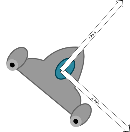
    /// </summary>
    /// <param name="p">the particle to initialize</param>
    /// <param name="where">the position on the screen that the particle should be
    /// </param>
    protected virtual void InitializeParticle(Particle p, Vector2 where)
    {
        // Initialize the particle with default values
        p.Initialize(where);
    }

Similarly, we will supply a default implementation for updating a particle. Our default approach is based on Newtonian physics:

    /// <summary>
    /// Updates the individual particles.  Can be overridden in derived classes
    /// </summary>
    /// <param name="particle">The particle to update</param>
    /// <param name="dt">The elapsed time</param>
    protected virtual void UpdateParticle(Particle particle, float dt)
    {
        // Update particle's linear motion values
        particle.Velocity += particle.Acceleration * dt;
        particle.Position += particle.Velocity * dt;

        // Update the particle's angular motion values
        particle.AngularVelocity += particle.AngularAcceleration * dt;
        particle.Rotation += particle.AngularVelocity * dt;

        // Update the time the particle has been alive 
        particle.TimeSinceStart += dt;
    }

This implementation works for a wide variety of particle systems, but it can be overridden by a derived particle system if something different is needed.

DrawableGameComponent Overrides

Now we can tackle the methods from DrawableGameComponent, which we’ll need to replace with our own custom overrides. First, we’ll load the texture in our LoadContent:

    /// <summary>
    /// Override the base class LoadContent to load the texture. once it's
    /// loaded, calculate the origin.
    /// </summary>
    /// <throws>A InvalidOperationException if the texture filename is not provided</throws>
    protected override void LoadContent()
    {
        // create the shared static ContentManager and SpriteBatch,
        // if this hasn't already been done by another particle engine
        if (contentManager == null) contentManager = new ContentManager(Game.Services, "Content");
        if (spriteBatch == null) spriteBatch = new SpriteBatch(Game.GraphicsDevice);

        // make sure sub classes properly set textureFilename.
        if (string.IsNullOrEmpty(textureFilename))
        {
            string message = "textureFilename wasn't set properly, so the " +
                "particle system doesn't know what texture to load. Make " +
                "sure your particle system's InitializeConstants function " +
                "properly sets textureFilename.";
            throw new InvalidOperationException(message);
        }
        // load the texture....
        texture = contentManager.Load<Texture2D>(textureFilename);

        // ... and calculate the center. this'll be used in the draw call, we
        // always want to rotate and scale around this point.
        origin.X = texture.Width / 2;
        origin.Y = texture.Height / 2;

        base.LoadContent();
    }

In addition to loading the texture, we make sure that our shared ContentManager and SpriteBatch are created, and calculate the Origin for the texture.

Our Update() method iterates over the particles and updates each one, invoking our UpdateParticle() method:

    /// <summary>
    /// Overriden from DrawableGameComponent, Update will update all of the active
    /// particles.
    /// </summary>
    public override void Update(GameTime gameTime)
    {
        // calculate dt, the change in the since the last frame. the particle
        // updates will use this value.
        float dt = (float)gameTime.ElapsedGameTime.TotalSeconds;

        // go through all of the particles...
        foreach (Particle p in particles)
        {

            if (p.Active)
            {
                // ... and if they're active, update them.
                UpdateParticle(p, dt);
                // if that update finishes them, put them onto the free particles
                // queue.
                if (!p.Active)
                {
                    freeParticles.Enqueue(p);
                }
            }
        }

        base.Update(gameTime);
    }

Notice that we only update the active particles. And if a particle is no longer active after we update it, we add it to the freeParticles queue to be reused.

Similarly, our Draw() method draws only the active particles:

    /// <summary>
    /// Overriden from DrawableGameComponent, Draw will use the static 
    /// SpriteBatch to render all of the active particles.
    /// </summary>
    public override void Draw(GameTime gameTime)
    {
        // tell sprite batch to begin, using the BlendState specified in
        // initializeConstants
        spriteBatch.Begin(blendState: blendState);

        foreach (Particle p in particles)
        {
            // skip inactive particles
            if (!p.Active)
                continue;
            
            spriteBatch.Draw(texture, p.Position, null, p.Color,
                p.Rotation, origin, 1, SpriteEffects.None, 0.0f);
        }

        spriteBatch.End();

        base.Draw(gameTime);
    }

Note that we provide a SpriteBlendState to the SpriteBatch.Begin() call, as different blend states can replicate different effects. We’ll see this in play soon.

Methods for Adding Particles to the System

Finally, we need some methods to add active particles into our system (otherwise, nothing will ever be drawn)! We’ll create two generic protected methods for doing this, which can be utilized by the derived particle system classes. We’ll start with one that adds particles at a specific position (defined by a Vector2):

    /// <summary>
    /// AddParticles's job is to add an effect somewhere on the screen. If there 
    /// aren't enough particles in the freeParticles queue, it will use as many as 
    /// it can. This means that if there not enough particles available, calling
    /// AddParticles will have no effect.
    /// </summary>
    /// <param name="where">where the particle effect should be created</param>
    protected void AddParticles(Vector2 where)
    {
        // the number of particles we want for this effect is a random number
        // somewhere between the two constants specified by the subclasses.
        int numParticles =
            RandomHelper.Next(minNumParticles, maxNumParticles);

        // create that many particles, if you can.
        for (int i = 0; i < numParticles && freeParticles.Count > 0; i++)
        {
            // grab a particle from the freeParticles queue, and Initialize it.
            Particle p = freeParticles.Dequeue();
            InitializeParticle(p, where);
        }
    }

This approach is especially useful for effects like explosions, which start with a bunch of particles, but don’t create more.

We may instead want to supply a region of screen space (say, a rectangle) to fill with particles:

    /// <summary>
    /// AddParticles's job is to add an effect somewhere on the screen. If there 
    /// aren't enough particles in the freeParticles queue, it will use as many as 
    /// it can. This means that if there not enough particles available, calling
    /// AddParticles will have no effect.
    /// </summary>
    /// <param name="where">where the particle effect should be created</param>
    protected void AddParticles(Rectangle where)
    {
        // the number of particles we want for this effect is a random number
        // somewhere between the two constants specified by the subclasses.
        int numParticles =
            RandomHelper.Next(minNumParticles, maxNumParticles);

        // create that many particles, if you can.
        for (int i = 0; i < numParticles && freeParticles.Count > 0; i++)
        {
            // grab a particle from the freeParticles queue, and Initialize it.
            Particle p = freeParticles.Dequeue();
            InitializeParticle(p, RandomHelper.RandomPosition(where));
        }
    }

This works well for something like rain and snow - we can add it just off-screen (say above the top of the screen) and let it flow over the screen based on its direction and speed.

Example Particle Systems

To create a particle system, we’ll derive a class from the ParticleSystem class and override its InitializeConstants(), and possibly its InitializeParticle() and UpdateParticle() methods. Let’s look at some examples:

Rain Particle System

This is a simplistic implementation of rain that is spawned in a predefined rectangle and falls to the bottom of the screen. The texture we’ll use is this drop

We start by defining a class extending the ParticleSystem:

/// <summary>
/// A class embodying a particle system emulating rain
/// </summary>
public class RainParticleSystem : ParticleSystem
{
    // TODO: Add Implementation
}

Inside this class, we’ll define a private Rectangle field to represent where the rain begins:

    // The source of the rain
    Rectangle _source;

And a boolean property to start and stop the rain:

    /// <summary>
    /// Determines if it is currently raining or not
    /// </summary>
    public bool IsRaining { get; set; } = true;

We’ll add a constructor that must also invoke the ParticleSystem constructor. We’ll supply the Rectangle to use for the source, and hard-code a maximum amount of particles (this may need to be tweaked for larger/smaller rain effects - if there aren’t enough particles there will be gaps in the rain):

    /// <summary>
    /// Constructs the rain particle system
    /// </summary>
    /// <param name="game">The game this particle system belongs to</param>
    /// <param name="source">A rectangle defining where the raindrops start</param>
    public RainParticleSystem(Game game, Rectangle source) : base(game, 5000)
    {
        _source = source;    
    }

We override the InitializeConstants() to set the number of particles that should be spawned with an AddParticles() method call, and the name of the texture to use:

    /// <summary>
    /// Initialize the particle system constants
    /// </summary>
    protected override void InitializeConstants()
    {
        // We'll use a raindrop texture
        textureFilename = "opaque-drop";

        // We'll spawn a large number of particles each frame 
        minNumParticles = 10;
        maxNumParticles = 20;
    }

Then we override the InitializeParticle() method of the base ParticleSystem to provide custom behavior for our rain particles. Basically, they just fall straight down. However, you could expand on this to add wind, etc.:

    /// <summary>
    /// Initializes individual particles
    /// </summary>
    /// <param name="p">The particle to initialize</param>
    /// <param name="where">Where the particle appears</param>
    protected override void InitializeParticle(Particle p, Vector2 where)
    {
        base.InitializeParticle(p, where);

        // rain particles fall downward at the same speed
        p.Velocity = Vector2.UnitY * 260;

        // rain particles have already hit terminal velocity,
        // and do not spin, so we don't need to set the other
        // physics values (they default to 0)

        // we'll use blue for the rain 
        p.Color = Color.Blue;

        // rain particles are small
        p.Scale = 0.1f;

        // rain particles need to reach the bottom of the screen
        // it takes about 3 seconds at current velocity/screen size
        p.Lifetime = 3;
    }

Finally, we’ll override the Update() method from DrawableGameComponent to add spawning new droplets every frame within our source rectangle:

    /// <summary>
    /// Override the default DrawableGameComponent.Update method to add 
    /// new particles every frame.  
    /// </summary>
    /// <param name="gameTime">An object representing the game time</param>
    public override void Update(GameTime gameTime)
    {
        base.Update(gameTime);

        // Spawn new rain particles every frame
        if(IsRaining) AddParticles(_source);
    }

Explosion Particle System

Another particle effect we see often in games is explosions. Let’s create an effect that will let us create explosions at specific points on-screen as our game is running. We’ll use this explosion texture.

We again start by defining a new class derived from ParticleSystem:

/// <summary>
/// A GameComponent providing a particle system to render explosions in a game
/// </summary>
public class ExplosionParticleSystem : ParticleSystem
{
    // TODO: Add implementation
}

Our constructor will invoke the base ParticleSystem constructor, but we’ll also ask for the maximum number of anticipated explosions the system needs to handle. As each explosion needs 20-25 particles, we’ll multiply that value by 25 to determine how many particles the system needs to have:

    /// <summary>
    /// Constructs a new explosion particle system
    /// </summary>
    /// <param name="game">The game to render explosions in</param>
    /// <param name="maxExplosions">The anticipated maximum number of explosions on-screen at one time</param>
    public ExplosionParticleSystem(Game game, int maxExplosions)
        : base(game, maxExplosions * 25)
    {
    }

The explosion will use an explosion texture, 20-25 particles per explosion, and additive blending. This blend mode means if two particles overlap, their colors are added together. As more particle combine, the combined color gets closer to white, meaning the center of the explosion will be bright white, but as the particles spread out they will get redder (as the texture is red and yellow). We’ll set these up by overriding the ParticleSystem.InitializeConstants() method:

    /// <summary>
    /// Set up the constants that will give this particle system its behavior and
    /// properties.
    /// </summary>
    protected override void InitializeConstants()
    {
        textureFilename = "explosion";

        // We'll use a handful of particles for each explosion
        minNumParticles = 20;
        maxNumParticles = 25;

        // Additive blending is very good at creating fiery effects.
        blendState = BlendState.Additive;
        DrawOrder = AdditiveBlendDrawOrder;
    }

We’ll also override ParticleSystem.InitializeParticle() to provide the default starting state for all particles:

    /// <summary>
    /// Initializes the particle <paramref name="p"/>
    /// </summary>
    /// <param name="p">The particle to initialize</param>
    /// <param name="where">Where the particle begins its life</param>
    protected override void InitializeParticle(Particle p, Vector2 where)
    {
        base.InitializeParticle(p, where);

        // Explosion particles move outward from the point of origin in all directions,
        // at varying speeds
        p.Velocity = RandomHelper.RandomDirection() * RandomHelper.NextFloat(40, 500);

        // Explosions should be relatively short lived
        p.Lifetime = RandomHelper.NextFloat(0.5f, 1.0f);

        // Explosion particles spin at different speeds
        p.AngularVelocity = RandomHelper.NextFloat(-MathHelper.PiOver4, MathHelper.PiOver4);

        // Explosions move outwards, then slow down and stop because of air resistance.
        // Let's set acceleration so that when the particle is at max lifetime, the velocity
        // will be zero.

        // We'll use the equation vt = v0 + (a0 * t). (If you're not familiar with
        // this, it's one of the basic kinematics equations for constant
        // acceleration, and basically says:
        // velocity at time t = initial velocity + acceleration * t)
        // We'll solve the equation for a0, using t = p.Lifetime and vt = 0.
        p.Acceleration = -p.Velocity / p.Lifetime;
    }

And we’ll also override the ParticleSystem.Update() method, so we can use custom logic to change the color and scale of the particle over its lifetime:

    /// <summary>
    /// We override the UpdateParticle() method to scale and colorize 
    /// explosion particles over time
    /// </summary>
    /// <param name="particle">the particle to update</param>
    /// <param name="dt">the time elapsed between frames</param>
    protected override void UpdateParticle(Particle particle, float dt)
    {
        base.UpdateParticle(particle, dt);

        // normalized lifetime is a value from 0 to 1 and represents how far
        // a particle is through its life. 0 means it just started, .5 is half
        // way through, and 1.0 means it's just about to be finished.
        // this value will be used to calculate alpha and scale, to avoid 
        // having particles suddenly appear or disappear.
        float normalizedLifetime = particle.TimeSinceStart / particle.Lifetime;

        // we want particles to fade in and fade out, so we'll calculate alpha
        // to be (normalizedLifetime) * (1-normalizedLifetime). this way, when
        // normalizedLifetime is 0 or 1, alpha is 0. the maximum value is at
        // normalizedLifetime = .5, and is
        // (normalizedLifetime) * (1-normalizedLifetime)
        // (.5)                 * (1-.5)
        // .25
        // since we want the maximum alpha to be 1, not .25, we'll scale the 
        // entire equation by 4.
        float alpha = 4 * normalizedLifetime * (1 - normalizedLifetime);
        particle.Color = Color.White * alpha;

        // make particles grow as they age. they'll start at 75% of their size,
        // and increase to 100% once they're finished.
        particle.Scale = particle.Scale * (.75f + .25f * normalizedLifetime);
    }

And finally, we need to allow the game to place explosion effects, so we’ll add a public method to do so:

    /// <summary>
    /// Places an explosion at location <paramref name="where"/>
    /// </summary>
    /// <param name="where">The location of the explosion</param>
    public void PlaceExplosion(Vector2 where) => AddParticles(where);

PixieParticleSystem

Another common use for particle systems is to have them emitted from an object in the game - i.e. the player, an enemy, or something the player can interact with. Let’s explore this idea by making a particle system that emits colored sparks that fall to the ground, like pixie dust. For this particle system, we’ll use this particle texture with a circular gradient.

Let’s start by defining an interface that can serve as our emitter representation. With an emitter, the particle starts in the same place as the emitter, so need to know its location in the game world, so a Vector2 we’ll name Position. Also, if the emitter is moving, we need to know the velocity it is moving at, as the particle will also start with that as its initial velocity, so we’ll add a second Vector2 named Velocity:

/// <summary>
/// An interface for the emitter of a particle system
/// </summary>
public interface IParticleEmitter
{
    /// <summary>
    /// The position of the emitter in the world
    /// </summary>
    public Vector2 Position { get; }

    /// <summary>
    /// The velocity of the emitter in the world
    /// </summary>
    public Vector2 Velocity { get; }
}

Then we start the particle system the same way as before, by defining a class that inherits from ParticleSystem:

/// <summary>
/// A particle system that drops "pixie dust" from an emitter
/// </summary>
public class PixieParticleSystem : ParticleSystem
{
    // TODO: Add implementation
}

We’ll want a list of emitters of our IParticleEmitter class so we know where to spawn those particles (this way we can have multiple pixies!):

    /// <summary>
    /// The emitter for this particle system
    /// </summary>
    public List<IParticleEmitter> Emitters { get; } = new List<IParticleEmitter>();

And we’ll construct our particle system with an expected number of pixies to support (with each using around 200 particles):

    /// <summary>
    /// Constructs a new PixieParticleSystem to support up to <paramref name="maxPixies"/> pixies
    /// </summary>
    /// <param name="game">The game this system belongs to</param>
    /// <param name="maxPixies">The maximum number of pixies to support</param>
    public PixieParticleSystem(Game game, int maxPixies): base(game, 200 * maxPixies) { }

We override ParticleSystem.InitializeConstants() to set up the particle system values:

    /// <summary>
    /// Set up the constants that will give this particle system its behavior and
    /// properties.
    /// </summary>
    protected override void InitializeConstants()
    {
        textureFilename = "particle";

        minNumParticles = 2;
        maxNumParticles = 5;

        blendState = BlendState.Additive;
        DrawOrder = AdditiveBlendDrawOrder;
    }

And ParticleSystem.InitializeParticle() to initialize individual particles:

    /// <summary>
    /// Initialize the particles
    /// </summary>
    /// <param name="p">The particle to initialize</param>
    /// <param name="where">Where the particle initially appears</param>
    protected override void InitializeParticle(Particle p, Vector2 where)
    {
        base.InitializeParticle(p, where);

        // The particle's initial velocity is the same as the emitter's
        p.Velocity = _emitter.Velocity;

        // The particle is affected by gravity
        p.Acceleration.Y = 400;

        // Randomize the particle size
        p.Scale = RandomHelper.NextFloat(0.1f, 0.5f);

        // Randomize the lifetime of the particles
        p.Lifetime = RandomHelper.NextFloat(0.1f, 1.0f);

        // The particle also is affected by air resistance;
        // lets' scale its X acceleration so it stops moving horizontally by the time it dies
        p.Acceleration.X = -p.Velocity.X / p.Lifetime;

    }

Since we’ll just use the build-in physics, we don’t need to override ParticleSystem.UpdateParticle(). But we will need to add new particles every frame, so we’ll override GameComponent.Update() to do so:

    /// <summary>
    /// Override Update() to add some particles each frame
    /// </summary>
    /// <param name="gameTime">An object representing game time</param>
    public override void Update(GameTime gameTime)
    {
        base.Update(gameTime);

        // Add particles at the emitter position
        AddParticles(_emitter.Position);
    }

This particle system can now be attached to any object implementing the IParticleEmitter interface, and the particles will be spawned wherever that emitter is in the game world!

Using Particle Systems

Now that we’ve defined some example particle systems, let’s see how we can put them into use.

Adding Rain

Let’s start with our RainParticleSystem, and add rain that runs down the screen. Since we don’t need to start/stop the rain for this simple example, all we need to do is construct the particle system and add it to the Game.Components list in the Game.Initialize() method:

    RainParticleSystem rain = new RainParticleSystem(this, new Rectangle(100, -10, 500, 10));
    Components.Add(rain);

Because the ExplosionParticleSystem inherits from DrawableGameComponent, we can add it to the Game.Components list. This means the game will automatically call its LoadContent(), Update() and Draw() methods for us. We could instead not add it to the components list, and manually invoke these ourselves.

Adding Explosions

Let’s say we want an explosion to appear on-screen wherever we click our mouse. We’ll use the ExplosionParticleSystem from the previous section to accomplish this.

First, because we will need to access this system in multiple methods of Game we’ll need to create a field to represent it in our Game class. We’ll also want to keep track of the previous mouse state:

    ExplosionParticleSystem explosions;
    MouseState oldMouseState;

And initialize it in our Game.Initialize() method:

    explosions = new ExplosionParticleSystem(this, 20);
    Components.Add(explosions);

We set the particle system to use up to 20 explosions on-screen at a time (as it takes about a second for an explosion to finish, this is probably more than enough, unless we have a very explosive game).

Next, we add some logic to our Update() method to update the mouse state, and determine if we need to place an explosion:

    MouseState newMouseState = Mouse.GetState();
    Vector2 mousePosition = new Vector2(mouseState.X, mouseState.Y);

    if(newMouseState.Left == ButtonState.Down && oldMouseState.Left == ButtonState.Up) 
    {
        explosions.PlaceExplosion(mousePosition);
    }

Now, whenever we click our mouse, we’ll see an explosion spawn!

Adding a Pixie

Rather than declare a class to represent the mouse and go through that effort, let’s just implement the IParticleEmitter interface directly on our Game. Thus, we need to implement Position and Velocity properties:

    public Vector2 Position { get; set; }

    public Vector2 Velocity { get; set; }

We’ll set these in the Game.Update() method, based on our mouse state:

    Velocity = mousePosition - Position;
    Position = mousePosition;

And we’ll need to add the particle system in the Game.Initialize() method, and set its emitter to the Game instance:

    PixieParticleSystem pixie = new PixieParticleSystem(this, this);
    Components.Add(pixie);

Now the mouse should start dripping a trail of sparks!

Refactoring as a Game Component

In this chapter we examined the idea of particle systems, which draw a large number of sprites to create visual effects within the game. We also went over the design of such a system we can use with MonoGame, leveraging the DrawableGameComponent base class and design approaches like hook methods, to make a relatively hands-off but flexible approach to create new custom particle systems. We also created three example particle systems to emulate rain, explosions, and a trail of sparks. You can use these as a starting point for creating your own custom particle systems to meet the needs of your games.

Tile Maps

I feel like we’ve passed that tree before…

via GIPHY

Subsections of Tile Maps

Introduction

While the earliest video games often featured worlds that were sized to the dimensions of the screen, it was not long before game worlds were to grow larger. This brought serious challenges to game development, as the platforms of the time did not have very large memory resources to draw upon.

A similar problem existed in storing raster images in early computers, where memory space was a premium. Remember, raster images have three or four color channels - Red, Green, Blue, and sometimes Alpha. If each channel is 8 bits, and an image is 13 x 21 pixels like the one below, our total memory consumption would be 8 x 4 x 13 x 21 = 8,736 bits, about 1 KB. But the image only contains three colors! Given that, can you think of a way to represent it with a smaller memory footprint?

Raster Image using a Color Palette Raster Image using a Color Palette

The answer they adopted was the use of a color palette, a collection of 8, 16, or 32 colors. This collection was 0-indexed (so the first color was represented by a 0, the next by a 1, and so on…). This meant you needed to sore 8 x 4 x 8 = 245 bits for a 8-color palette, and the actual image could be represented as a list of 3-bit color keys (3 bits can represent 0-7, the full range of keys for a 8-color palette). So we only need an additional 3 x 13 x 21 = 819 bits to represent the image data. The actual image therefore could be represented by only 1,064 bits - about 1/8th a KB. The memory savings grow larger the larger the image represented.
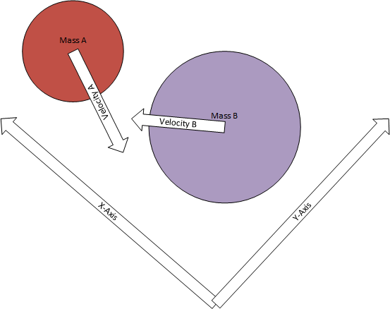
With the concept of palettized image formats in mind, let’s look at an example of an early game - Super Mario Bros. Do you notice anything about the game world that harkens back to our earlier use of palettes?

Super Mario Bros Super Mario Bros

Notice how so much of the scene seems to be the same texture repeated? Much like the color palette applies a collection of colors on a regular grid, a tile engine applies a collection of tile textures on a regular grid. This allows a large level to be drawn with only a handful of textures. Moreover, these textures are typically stored in a texture atlas (i.e. all the tiles appear in a single texture).

Let’s look at how we can implement this strategy in our own games.

Tilemap Concepts

Let’s start from a purely conceptual level, with some diagrams using tile assets created by Eris available from OpenGameArt. A tile map could be thought of as a grid of tiles, as demonstrated in this image:

Tile map Example Tile map Example

Along with the map is the tile set, which defines the individual tiles that can be used within the map, i.e.:

Tile set Example Tile set Example

We assign a number to each tile in the tile set:

Numbered tile set Numbered tile set

We can then specify what tile fills a grid cell in the tile map with the same number, i.e.:

Tile map with numbered tiles Tile map with numbered tiles

You can see that a relatively complex map can be quickly assembled from a relative handful of tiles. Looking at the image above, you may naturally consider a 2-dimensional array:

int map = new int[,] 
{
  {-1,-1,-1,-1,46,-1,-1,-1,-1,-1,-1,-1,-1,-1,-1,-1,-1,-1,-1,-1},
  {-1,-1,52,53, 1,-1,-1,-1, 3,45, 1, 3,-1,37,38,-1,-1,-1,-1,-1},
  {52,53,57,47, 4,-1,-1,-1,-1,44,23,-1,-1,-1,-1,-1,-1,-1,-1,-1},
  {24,25, 4,48, 4,40,38,-1,-1,44,-1,-1,-1,-1,-1,-1,37,40,38,-1}
  {12,57,24,25, 4,-1,-1,-1,-1,44,56, 1,-1,-1,-1,-1,-1,-1,-1,-1},
  {-1,12, 4,29,30,25,-1,52,53, 0,61, 7,39,25,-1,-1,-1,-1,-1,-1},
  {-1,62, 1, 1, 1, 1, 1, 1, 1, 1, 1,45, 1, 1, 1,62,-1,-1,28,-1},
  {-1,-1,-1,-1,-1,23,-1,-1,-1,-1,-1,44,-1,-1,23,-1,-1, 2,62,-1}
}

And to draw the map, we would iterate over this array, drawing the corresponding tile from the tileset:

for(int x = 0; x < map.GetLength(0); x++)
{
  for(int y = 0; y < map.GetLength(1); y++)
  {
    int tileIndex = map[x,y];
    if(tileIndex == -1) continue; // -1 indicates no tile, so skip drawing
    DrawTile(x, y, tileIndex);
  }
}

So you can see we need to implement classes corresponding to 1) the set of available tiles, and 2) the tile map, which is really just a collection of indices for the tile set. But before we do that, we need to discuss 2d and 1d arrays in a bit more detail.

2D and 1D Arrays

Let’s talk briefly about how a 2d array is actually stored in memory. We like to think of it as looking something like this visualization:

2D array visualization 2D array visualization

But in reality, it is stored linearly, like this:

2D array in memory 2D array in memory

To access a particular element in the array, the 2d coordinates must be transformed into a 1d index. Note that each row follows the proceeding rows, so the starting index of each row would be the width of the row, plus the x-coordinate, i.e. the index of $ (3,1) $ would be $ 1 * width + 3 $:

Accessing (3,1) Accessing (3,1)

This can be generalized into the equation:

$$ i = y * width + x $$

And the reverse operation, converting an index into 2d coordinates, would be:

$$ x = i \\\% width $$ $$ y = i / width $$

Info

Note that we are using integer division and modulus in these equations, as the $ y $ value is the number of full rows (i.e. $ width $), and the $ y $ is the distance into the partial row (i.e. the remainder).

Thus, all we need to treat a 1d array as a 2d array (in addition to the data) is the width of the array. The height is only needed to calculate the array size (and thus the upper bound), which would be:

$$ size = width * height $$

The C# Multidimensional Array simply builds on this concept, wrapping the array data in an object (note that for each dimension, you will have a corresponding size for that dimension, i.e. width, height, and depth for a 3d array).

Efficiency and 2d Arrays

Now, a note on efficiency - iterating through a C# multi-dimensional array is slower than the corresponding 1d array, as the interpreter optimizes 1d array operations (see What is Faster In C#: An int[] or an int[,] for a technical discussion of why). With that in mind, for a game we’ll always want to use a 1d array to represent 2d data.

A second note on efficiency. The order in which you iterate over the array also has an impact on efficiency. Consider an arbitrary 2d array arr implemented as a 1d array with width and height.

What would be the difference between loop 1:

int sum = 0;
for(int x = 0; x < width; x++)
{
  for(int y = 0; y < height; y++)
  {
    sum += arr[y * width + x]
  }
}

And loop 2:

int sum = 0;
for(int y = 0; y < height; y++)
{
  for(int x = 0; x < width; x++)
  {
    sum += arr[y * width + x]
  }
}

You probably would think they are effectively the same, and logically they are - they both will compute the sum of all the elements in the array. But loop 2 will potentially run much faster. The reason comes down to a hardware detail - how RAM and the L2 and L1 caches interact.

When you load a variable into a hardware register to do a calculation, it is loaded from RAM. But as it is loaded, the memory containing it, and some of the memory around it is also loaded into the L2 and L1 caches. If the next value in memory you try to access is cached, then it can be loaded from the cache instead of RAM. This makes the operation much faster, as the L2 and L1 caches are located quite close to the CPU, and RAM is a good distance away (possibly many inches!).

Consider the order in which loop 1 accesses the array. It first accesses the first element in the first row. Then the first element in the second row, and then the first element in the third row, then the second element in the first row, and so on… You can see this in the figure below:

Loop 1 access order Loop 1 access order

Now, consider the same process for Loop 2:

Loop 2 access order Loop 2 access order

Notice how all the memory access happens linearly? This makes the most efficient use of the cached data, and will perform much better when your array is large.

A Basic Tile Engine

Now that we have a good sense of what a tile map consists of, as well as how to effectively use a 1-dimensional array as a 2-dimensional array, let’s discuss actual implementations. As we discussed conceptually, we need: 1) a set of tiles, and 2) the arrangement of those tiles into a map.

Let’s start by thinking about our tiles. To draw a tile, we need to know:

  1. What texture the tile appears in
  2. The bounds of the tile in that texture
  3. Where the tile should appear on screen

To determine this information, we need several other items:

  • The width of the map in tiles
  • The height of the map in tiles
  • The width of a tile in pixels
  • The height of a tile in pixels

And we can simplify the problem with some assumptions:

  • Tiles are all the same size
  • The tileset image has the tiles organized side-by-side in a grid pattern

Representing the Map

Given this understanding, we can determine some fields we’ll need to keep track of the data:

/// <summary>The map filename</summary>
private string _mapFilename;

/// <summary>The tileset texture</summary>
private Texture2D _tilesetTexture;

/// <summary>The map and tile dimensions</summary>
private int _tileWidth, _tileHeight, _mapWidth, _mapHeight;

/// <summary>The tileset data</summary>
private Rectangle[] _tiles;

/// <summary>The map data</summary>
private int[] _map;

Loading the Data

Now let’s turn our attention to how we can populate those fields. Let’s first consider how we might write the data for a tilemap in a text file:

tileset
64, 64
10, 10
3, 3, 3, 3, 3, 3, 3, 3, 3, 3, 4, 4, 4, 2, 2, 2, 2, 2, 2, 3, 3, 2, 4, 4, 1, 4, 2, 2, 2, 3, 3, 2, 2, 2, 2, 4, 4, 4, 2, 3, 3, 2, 2, 2, 2, 2, 2, 1, 2, 3, 3, 3, 1, 3, 2, 2, 2, 4, 4, 3, 3, 2, 2, 3, 2, 3, 2, 2, 4, 4, 3, 2, 2, 3, 2, 3, 2, 2, 2, 3, 3, 3, 3, 3, 3, 3, 2, 2, 2, 3, 3, 3, 3, 3, 3, 3, 3, 3, 3, 3

In this example, the first line is the name of the tileset image file (which is loaded through the content pipeline, so it has no extension). The second line is the width and height of a tile, and the third line is the width and height of the map (measured in tiles). The last line is the indices of the tiles from the tileset image.

Loading the data from this file requires a method like this:

public void LoadContent(ContentManager content)
{
    // Read in the map file
    string data = File.ReadAllText(Path.Join(content.RootDirectory, _mapFilename));
    var lines = data.Split('\n');

    // First line is tileset image file name 
    var tilesetFileName = lines[0].Trim();
    _tilesetTexture = content.Load<Texture2D>(tilesetFileName);

    // Second line is tile size
    var secondLine = lines[1].Split(',');
    _tileWidth = int.Parse(secondLine[0]);
    _tileHeight = int.Parse(secondLine[1]);

    // Now that we know the tile size and tileset
    // image, we can determine tile bounds
    int tilesetColumns = _tilesetTexture.Width / _tileWidth;
    int tilesetRows = _tilesetTexture.Height / _tileWidth;
    _tiles = new Rectangle[tilesetColumns * tilesetRows];
    for (int y = 0; y < tilesetRows; y++)
    {
        for (int x = 0; x < tilesetColumns; x++)
        {
            _tiles[y * tilesetColumns + x] = new Rectangle(
                x * _tileWidth, // upper left-hand x cordinate
                y * _tileHeight, // upper left-hand y coordinate
                _tileWidth, // width 
                _tileHeight // height
                );
        }
    }

    // Third line is map size (in tiles)
    var thirdLine = lines[2].Split(',');
    _mapWidth = int.Parse(thirdLine[0]);
    _mapHeight = int.Parse(thirdLine[1]);

    // Fourth line is map data
    _map = new int[_mapWidth * _mapHeight];
    var fourthLine = lines[3].Split(',');
    for(int i = 0; i < _mapWidth * _mapHeight; i++)
    {
        _map[i] = int.Parse(fourthLine[i]);
    }
}

While there is a lot going on here, it is also mostly basic File I/O based on the structure of the file.

Rendering the Tilemap

Finally, drawing the map involves iterating over the data and invoking SpriteBatch.Draw() for each tile that needs drawn.

public void Draw(GameTime gameTime, SpriteBatch spriteBatch)
{
    for(int y = 0; y < _mapHeight; y++)
    {
        for(int x = 0; x < _mapWidth; x++) 
        {
            // Indexes start at 1, so shift for array coordinates
            int index = _map[y * _mapWidth + x] - 1;
            // Index of -1 (shifted from 0) should not be drawn
            if (index == -1) continue;
            spriteBatch.Draw(
                _tilesetTexture,
                new Vector2(
                    x * _tileWidth,
                    y * _tileHeight
                ),
                _tiles[index],
                Color.White
            );
        }
    }
}

Organizing these fields and methods into a class gives us a simple tile engine. This can be expanded to address a lot of different games’ needs. However, it does require building the map file by hand, using raw tile indices. This gets challenging quickly, which leads us to our next topic - using a tilemap editor.

Tiled Editor

Once we start thinking in terms of large, complex maps editing the map by hand becomes a daunting task. Instead, we want a tool to edit the map visually. One of the best free tools to do so is the Tiled Map Editor. Tiled is free, open-source, and widely used in the games industry. It allows you to quickly create a tilemap by importing tilesets and drawing the map using a suite of visual tools. You can read more about Tiled and its functionality in the documentation and covered in this video series by GamesfromScratch.

However, it adds additional concepts to tile maps that we have not yet discussed.
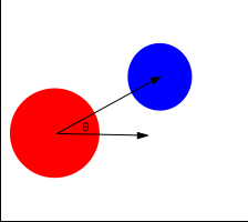
Properties

Because Tiled is intended to be usable in a wide variety of games, it allows properties to be defined on almost everything. In Tiled, properties are simply key/value pairs, i.e. "Opacity" might be set to 0.5. There are no pre-defined keys, instead you decide what properties you need for your game. The properties are stored in collections, essentially a Dictionary<string, string>, which is how we’ll interpret them in our C# code.

Tilesets

Tilesets are implemented in a similar fashion to our earlier discussions, however:

  1. An index of 0 represents “no tile”. This allows you to used unsigned integers as a tile index
  2. More than one tileset can be used. Each new tileset begins with the next index. So if we have two tilesets with eight tiles each, the first tileset will have indices 1-8, and the second will have 9-16.
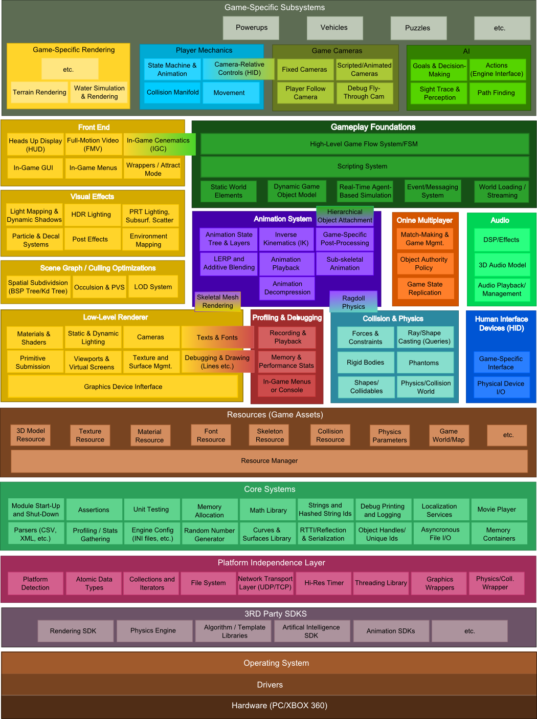
  3. Individual tiles can have properties - which is commonly used for collision information, to identify solid surfaces and platforms, etc.

Map Layers

Instead of a single 2d array of tiles, Tiled allows you to create maps with multiple layers, each with its own 2d array. This can be used in a variety of ways:

  1. To create a foreground and background layer, a common approach in top-down views because it allows the player to walk behind foreground elements (i.e. the base of a tree is in the background layer, but the branches and crown is in the foreground)
  2. To implement parallax scrolling - where layers scroll at different speeds to create the illusion of depth. We discuss the implementation details of parallax scrolling in chapter 8.
  3. To create complex, multi-level dungeons where players can move between layers

Conceptually, a map layer is implemented the same way as the simple tile map we discussed earlier. It is a 2d array of tile indices implemented as a 1d array, along with storing the width, height, and any properties that apply to the entire layer.

In addition to layers of tiles, Tiled also supports image and object layers.

Image Layers

An image layer represents an image that is not a tile. This can be used for large bitmaps that cover the entire layer, or smaller ones that appear in a particular spot. Images can also repeat to fill the layer or defined space.

Object Layers

In addition to tiles, and images, Tiled allows you to place “objects” in a map. These are represented by boxes that do not correspond to the grid system of the tiles. Objects are simply a rectangle plus properties, and can be used to represent anything you need to place in the game world - spawn positions, event triggers, doors, etc.

Objects are organized into object layers, which are essentially a collection of objects.

Working with Tiled in MonoGame

Tiled uses an XML file format, TMX. Thus, you can load a TMX file and then parse it with an XML parsing library. In fact, Tiled was released with an example engine that does this, created by Kevin Gadd. This was later converted into C# for use with XNA by Stephen Balanger and Zach Musgrave.

I further converted this for use with the current version of MonoGame, with additional documentation. It can be found on GitHub.

Summary

In this chapter we learned about tile maps, an important technique for creating large game worlds with small memory footprints. We also examined the Tiled map editor and saw an example of loading a Tiled map. However, this approach used traditional File I/O. In our next chapter, we’ll learn how to use the Content Pipeline to process the TMX file directly.

Content Pipeline

Get Your Assets into the Game!

via GIPHY

Subsections of Content Pipeline

Introduction

The creation of assets (textures, audio, models, etc) is a major aspect of game development. In fact, asset creators account for most of a game development team (often a 90/10 split between asset creators and programmers). So creating and using assets is a very important part of creating games!

To make this process manageable, most assets are created with other software tools - editors specific to the kind of asset we are dealing with. Asset creators become quite proficient with these tools, and provide their assets in a save file form specific to one of these tools.

We can load these files directly in our game, especially if our game targets Windows, where we have a lot of available supporting libraries. But those file formats are tailored towards the needs of the editor program - they often contain data we don’t need, or format it in a way that must be transformed to use in our games. And the processing involved in loading can be a lot more involved than we like, causing long load times.

One way around this is the use of a Content Pipeline which transforms assets from an editor-specific file format to one optimized for our games. This happens during the build process, so the transformed asset files are bundled with our executable, ready to be utilized.

This chapter will describe the content pipeline approach specific to XNA.

The Content Pipeline

As we described in the introduction, the XNA Content Pipeline’s purpose is to transform asset files (content) in to a form most readily useable by our games. It is implemented as a separate build step that is run every time we compile our game. In fact, each XNA game is actually two projects - the Content project, and the Game project.

The pipeline is broken up into several steps:

  1. Importing the asset data
  2. Processing the asset data
  3. Serializing the asset data
  4. Loading the serialized asset data

You can see the process here:

XNA Content Pipeline XNA Content Pipeline

Each of these steps is accomplished by a different class, and the data passed between the steps is also typically done as an object (defined by a class).

The two projects share a single file - the .xnb file generated from the content. This is essentially an object that has been serialized as binary data by the content serializer class, and will be deserialized back into an object by the content loader class.

Info

An important aspect of the serialization process is that the object that is serialized into a .xnb file and the one deserialized from it don’t have to be the defined by the same class! For example, in the content pipeline simple 2d textures are represented by a Texture2DContent instance, while in runtime projects we load the serialized data into a Texture2D instance. The key is that the serialized data is the same for both.

Extending the Pipeline

You might be wondering why the content pipeline in XNA was created this way - with importers, processors, content writers, and content readers. The answer is simple - modularity. If you want to load a new image format that the TextureImporter does not handle, you can write your own custom importer to load its data into a TextureContent object, and then still use the existing TextureProcessor and serialization process.

Alternatively, you may want to handle a new content type that has no associated classes in XNA at all. In this case, you will need to write a custom importer, processor, writer, and reader.

The basic tilemap we worked with in the previous chapter is a good candidate for learning how to create our own custom content importers and processors. We’re already familiar with it, and it has just the right amount of complexity to show off important ideas about customizing the content pipeline without becoming unwieldy.

We’ll start by thinking about what data we really need in our game - this defines our runtime class. Basically, we need to keep our Draw() method and any information needed within it. But the Load() method we can get rid of entirely! Our stripped-down class might look something like:

namespace ExampleGame
{
    public class BasicTilemap
    {
        /// <summary>
        /// The map width
        /// </summary>
        public int MapWidth { get; init; }

        /// <summary>
        /// The map height
        /// </summary>
        public int MapHeight { get; init; }

        /// <summary>
        /// The width of a tile in the map
        /// </summary>
        public int TileWidth { get; init; }

        /// <summary>
        /// The height of a tile in the map
        /// </summary>
        public int TileHeight { get; init; }

        /// <summary>
        /// The texture containing the tiles
        /// </summary>
        public Texture2D TilesetTexture { get; init; }

        public Rectangle[] Tiles { get; init; }

        public int[] TileIndices { get; init; }

        public void Draw(GameTime gameTime, SpriteBatch spriteBatch)
        {
            for(int y = 0; y < MapHeight; y++)
            {
                for(int x = 0; x < MapWidth; x++)
                {
                    // Indices start at 1, so shift by 1 for array coordinates
                    int index = TileIndices[y * MapWidth + x] - 1;

                    // Index of -1 (shifted from 0) should not be drawn
                    if (index == -1) continue;

                    // Draw the current tile
                    spriteBatch.Draw(
                        TilesetTexture,
                        new Rectangle(
                            x * TileWidth,
                            y * TileHeight,
                            TileWidth,
                            TileHeight
                            ),
                        Tiles[index],
                        Color.White
                        );
                }
            }

        }
    }
}

We also need to provide a content pipeline version of our tilemap class. For this one, we won’t need any of the functionality of our Draw() or Load() methods (as we don’t need to draw in the pipeline, and we’ll move responsibility for loading into our content importer and processor). So really, we only nee to provide a class to contain all the data contained within our tilemap file. To keep things simple, we’ll use the same file format we did in the previous chapter, but we’ll give the file a new extension: .tmap (it will still be a text file). Such a class might look like:

namespace BasicTilemapPipeline
{  

    [ContentSerializerRuntimeType("ExampleGame.BasicTilemap, ExampleGame")]
    public class BasicTilemapContent
    {
        /// <summary>Map dimensions</summary>
        public int MapWidth, MapHeight;

        /// <summary>Tile dimensions</summary>
        public int TileWidth, TileHeight;

        /// <summary>The tileset texture</summary>
        public Texture2DContent TilesetTexture;

        /// <summary>The tileset data</summary>
        public Rectangle[] Tiles;

        /// <summary>The map data</summary>
        public int[] TileIndices;

        /// <summary>The map filename</summary>
        [ContentSerializerIgnore]
        public string mapFilename;

        /// <summary> The tileset image filename </summary>
        [ContentSerializerIgnore]
        public String TilesetImageFilename;      
    }
}

Note the use of the attributes [ContentSerializerRuntimeType] on the class, and [ContentSerializerIgnore]. By using these attributes and following a few simple rules, we avoid the need to write a custom content serializer and loader to write and read our specific .xnb file.

The [ContentSerializerRuntimeType] identifies what the runtime version of this class will be, as a string containing the fully-qualified class name (the class name with all its namespaces), followed by a comma and the namespaces of the class. This is specified as a string so that our content project doesn’t need to have a reference to our game project (or a separate library project) where the class is defined.

The [ContentSerializerIgnore] attribute identifies attributes (properties and fields) of the content pipeline version that do not have a corresponding attribute in the runtime version. Thus, these will not be written to the .xnb file. For all other attributes, they need to be declared in the same order in both classes. For the most part, they also need to be the same Type (with the exception of any classes that have distinct content pipeline/runtime forms, like the Texture2DContent/Texture2D).

Also, all members that will be serialized/deserialized need to be declared public. They can be either fields or properties, and you can mix-and-match. Here in the runtime I am using properties with an init accessor so that each property can only be set once, during the deserialization process. In the pipeline version I am using fields. This is mostly to demonstrate the flexibility - feel free to use whatever you feel most comfortable with.

Custom Importer

An importer is a class that extends the ContentImporter<T> class and overrides its Import() method. Notice the class is a template class (the <T> in the definition). When we define our own class, we need to replace that T with the specific class we want the importer to populate. In our case, this is the BasicTilemapContent we defined in the previous page.

All importers need to override the Import() method. This method takes a filename (the filename of the asset) as an argument, and returns the class specified in the template. The purpose of an importer is to read the important parts of the asset file and load them into an object that gets passed down the pipeline, to the content processor.

For our example, let’s revisit our tilemap file, now named example.tmap:

tileset.png
64,64
10,10
3, 3, 3, 3, 3, 3, 3, 3, 3, 3, 4, 4, 4, 2, 2, 2, 2, 2, 2, 3, 3, 2, 4, 4, 1, 4, 2, 2, 2, 3, 3, 2, 2, 2, 2, 4, 4, 4, 2, 3, 3, 2, 2, 2, 2, 2, 2, 1, 2, 3, 3, 3, 1, 3, 2, 2, 2, 4, 4, 3, 3, 2, 2, 3, 2, 3, 2, 2, 4, 4, 3, 2, 2, 3, 2, 3, 2, 2, 2, 3, 3, 3, 3, 3, 3, 3, 2, 2, 2, 3, 3, 3, 3, 3, 3, 3, 3, 3, 3, 3

To quickly review, the first line is the name of our tileset image file, the second is the dimensions of a single tile (in the form width,height), the third is the size of our map in tiles (again, width,height), and the fourth is the indices of the individual tiles (with a 0 representing no tile).

Now we want to load that file’s information into a TilemapContent object in our importer:

using System.IO;
using System.Linq;
using Microsoft.Xna.Framework.Content.Pipeline;
using Microsoft.Xna.Framework.Content.Pipeline.Graphics;

namespace BasicTilemapPipeline
{
    /// <summary>
    /// An importer for a basic tilemap file. The purpose of an importer to to load all important data 
    /// from a file into a content object; any processing of that data occurs in the subsequent content
    /// processor step. 
    /// </summary>
    [ContentImporter(".tmap", DisplayName = "BasicTilemapImporter", DefaultProcessor = "BasicTilemapProcessor")]
    public class BasicTilemapImporter : ContentImporter<BasicTilemapContent>
    {
        public override BasicTilemapContent Import(string filename, ContentImporterContext context)
        {
            // Create a new BasicTilemapContent
            BasicTilemapContent map = new();

            // Read in the map file and split along newlines 
            string data = File.ReadAllText(filename);
            var lines = data.Split('\n');

            // First line in the map file is the image file name,
            // we store it so it can be loaded in the processor
            map.TilesetImageFilename = lines[0].Trim();

            // Second line is the tileset image size
            var secondLine = lines[1].Split(',');
            map.TileWidth = int.Parse(secondLine[0]);
            map.TileHeight = int.Parse(secondLine[1]);

            // Third line is the map size (in tiles)
            var thirdLine = lines[2].Split(',');
            map.MapWidth = int.Parse(thirdLine[0]);
            map.MapHeight = int.Parse(thirdLine[1]);

            // Fourth line is the map data (the indices of tiles in the map)
            // We can use the Linq Select() method to convert the array of strings
            // into an array of ints
            map.TileIndices = lines[3].Split(',').Select(index => int.Parse(index)).ToArray();

            // At this point, we've copied all of the file data into our
            // BasicTilemapContent object, so we pass it on to the processor
            return map;
        }
    }
}

We decorate the class with the [ContentImporter] attribute, which specifies a file extension this importer applies to (which is why we used the .tmap extension instead of the .txt we did previously), a name used by the MonoGame Content Editor to identify the importer, and also the suggested Content Processor to use next in the pipeline.

The bulk of the Import() method is just the parts of the Load() method from our original tilemap project that populated variables based on the contents of the file. The loading of the texture and the determination of tile bounds we save for the content processor (though we save the image filename so we will have it then). The populated BasicTilemapContent object will be passed to it next.

Custom Processor

A processor is a class that extends the ContentProcessor<TInput, TOutput>class and overrides its Process() method. Like the importer, this is a template class, but with two templates! The TInput identifies the class coming into the Process() method as an argument, and the TOutput identifies the class being returned from the method. Not that these don’t have to be different classes - in our case, we’ll continue using the TilemapContent class we defined earlier, and just populate a few more of its properties:

namespace SimpleTilemapPipeline
{
    /// <summary>
    /// Processes a BasicTilemapContent object, building and linking the associated texture 
    /// and setting up the tile information.
    /// </summary>
    [ContentProcessor(DisplayName = "BasicTilemapProcessor")]
    public class BasicTilemapProcessor : ContentProcessor<BasicTilemapContent, BasicTilemapContent>
    {
        public override BasicTilemapContent Process(BasicTilemapContent map, ContentProcessorContext context)
        {
            // We need to build the tileset texture associated with this tilemap
            // This will create the binary texture file and link it to this tilemap so 
            // they get loaded together by the ContentProcessor.  
            //map.TilesetTexture = context.BuildAsset<Texture2DContent, Texture2DContent>(map.TilesetTexture, "Texture2DProcessor");
            map.TilesetTexture = context.BuildAndLoadAsset<TextureContent, Texture2DContent>(new ExternalReference<TextureContent>(map.TilesetImageFilename), "TextureProcessor");

            // Determine the number of rows and columns of tiles in the tileset texture            
            int tilesetColumns = map.TilesetTexture.Mipmaps[0].Width / map.TileWidth;
            int tilesetRows = map.TilesetTexture.Mipmaps[0].Height / map.TileWidth;

            // We need to create the bounds for each tile in the tileset image
            // These will be stored in the tiles array
            map.Tiles = new Rectangle[tilesetColumns * tilesetRows];
            context.Logger.LogMessage($"{map.Tiles.Length} Total tiles");
            for(int y = 0; y < tilesetRows; y++)
            {
                for(int x = 0; x < tilesetColumns; x++)
                {
                    map.Tiles[y * tilesetColumns + x] = new Rectangle(
                        x * map.TileWidth,
                        y * map.TileHeight,
                        map.TileWidth,
                        map.TileHeight
                        );
                }
            }
            
            // Return the fully processed tilemap
            return map;
        }
    }
}

Something very interesting happens here. The processor builds and loads the tilemap texture into the Texture2DContent member. This means that when we use Content.Load<T>() to load the .xnb file, it will already contain the texture. We don’t need any additional steps in our game to load dependent assets. This makes complex, multi-file assets much easier to work with!

This is one of the most important abilities of the ContentProcessorContext object supplied to each processor - it allows them to build additional assets (External References in XNA lingo) without requiring those assets to be explicitly added to the content project. We can also supply content processor parameters, or even specify a different importer and processor to use for that dependant asset to the build method.

Info

In this example, we used a Texture2DContent variable and the context.BuildAndLoadAsset<Texture2DContent>() method to build and load the asset. This approach embeds the dependent asset into the resulting map object. But what if we wanted to use the same texture in multiple maps? In that case, we could change our member to be a ExternalReference<Texture2DContent> and use the context.BuildAsset<Texture2D>() method to build it. The benefit of this approach is that the texture is not embedded in the map’s xnb file, but rather gets its own file. That way the ContentProcessor only needs load its data once - it’s basically the flyweight pattern for external resources!

The other task our processor does is determine the source bounds for each of our four tiles - this code is directly taken from the earlier tilemap example’s Load() method.

As with our importer and content class we are also using an attribute - in this case [ContentProcessor]. It simply defines a name for the MonoGame Content Builder to display for the processor.

Using in a Game

Using our newly-created custom pipeline in a game we are building is not terribly complicated, but does require some understanding of how projects in Visual Studio interact. Perhaps most important to this is understanding that the Content.mgcb file in your game solution is actually another Visual Studio project! As such, it can reference other project, just like the C# projects you are used to. This can be done through the MGCB Editor. Just select the content project itself, and scroll down in the properties until you find the References value:

Selecting the MGCB Project References Selecting the MGCB Project References

This opens a dialog you can use to add custom pipeline projects as references to your MGCB content project (in the form of .DLL files). Just browse to their location (and remember, they need to be inside your solution folder if you want them committed to your repository).

The references dialog The references dialog

If your content pipeline project is in the same solution as your game project, you can browse to your content pipeline’s /bin folder to find it.

Alternatively you can set your content project as a dependency of your game project, which will ensure the custom pipeline project built and the DLL is copied into your game project’s /bin folder before the content project is built. This will keep everything up-to-date, but you don’t need the DLL to run your game (so your /bin folder is slightly bloated by this approach). This extra reference can be removed before releasing though, and it is often worth it to ensure changes to your custom pipeline are being applied in development.

You can also manually add the reference to your Content.mgcb file (it is just a text file, after all). The one for our example looks like:

#----------------------------- Global Properties ----------------------------#

/outputDir:bin/$(Platform)
/intermediateDir:obj/$(Platform)
/platform:Windows
/config:
/profile:Reach
/compress:False

#-------------------------------- References --------------------------------#

/reference:..\..\BasicTilemapPipeline\bin\Debug\net6.0\BasicTilemapPipeline.dll

#---------------------------------- Content ---------------------------------#

#begin example.tmap
/importer:BasicTilemapImporter
/processor:BasicTilemapProcessor
/build:example.tmap

Once the reference is added using any of these methods, you can add your .tmap file to the content project, and it should automatically select the BasicTilemapImporter and BasicTilemapProcessor (You can also manually specify it in the .mgcb project file as shown above):

The importer and processor in the MGCBEditor The importer and processor in the MGCBEditor

Once added, you can build the project, and an example.xnb file will be built and deposited in the /bin/Content folder.

Using it in our game simply requires using Content.Load<BasicTilemap>("example.tmap") to load the tilemap into a variable, and invoking its Draw() method to render it.

The Context Object

You probably noticed that we supply a context object to both our importer and processor - a ContentImporterContext for the importer and a ContentProcessorContext for the processor.

They both contain a Logger property, which allows us to log messages during the build process of our assets. This is important, as we can’t use breakpoints in a content project. So instead, we often use context.Logger.LogMessage(), context.Logger.LogImportantMessage(), and context.Logger.LogWarning() to let us expose the inner workings of our context pipeline.

We also used the ContentProcessorContext to build an external reference - the texture. In addition to this important functionality, it also exposes a dictionary of parameters supplied to the content processor. Essentially, any public property will be exposed as a processor parameter. For example, if we add this to our processor class:

        /// <summary>
        /// Applies a scaling factor to tiles while processing the tilemap
        /// </summary>
        public float Scale { get; set; } = 1.0f;

The Scale property will now appear in the MGCB Editor:

The Scale BasicTilemapProcessor Property The Scale BasicTilemapProcessor Property

And, if we were to set it in the editor, the new value would be accessible in the processor, so we can use it in our Process() method. Here’s the revised processor:

namespace SimpleTilemapPipeline
{
    /// <summary>
    /// Processes a BasicTilemapContent object, building and linking the associated texture 
    /// and setting up the tile information.
    /// </summary>
    [ContentProcessor(DisplayName = "BasicTilemapProcessor")]
    public class BasicTilemapProcessor : ContentProcessor<BasicTilemapContent, BasicTilemapContent>
    {
        /// <summary>
        /// A scaling parameter to make the tilemap bigger
        /// </summary>
        public float Scale { get; set; } = 1.0f;

        public override BasicTilemapContent Process(BasicTilemapContent map, ContentProcessorContext context)
        {
            // We need to build the tileset texture associated with this tilemap
            // This will create the binary texture file and link it to this tilemap so 
            // they get loaded together by the ContentProcessor.  
            //map.TilesetTexture = context.BuildAsset<Texture2DContent, Texture2DContent>(map.TilesetTexture, "Texture2DProcessor");
            map.TilesetTexture = context.BuildAndLoadAsset<TextureContent, Texture2DContent>(new ExternalReference<TextureContent>(map.TilesetImageFilename), "TextureProcessor");

            // Determine the number of rows and columns of tiles in the tileset texture
            int tilesetColumns = map.TilesetTexture.Mipmaps[0].Width / map.TileWidth;
            int tilesetRows = map.TilesetTexture.Mipmaps[0].Height / map.TileWidth;

            // We need to create the bounds for each tile in the tileset image
            // These will be stored in the tiles array
            map.Tiles = new Rectangle[tilesetColumns * tilesetRows];
            context.Logger.LogMessage($"{map.Tiles.Length} Total tiles");
            for(int y = 0; y < tilesetRows; y++)
            {
                for(int x = 0; x < tilesetColumns; x++)
                {
                    // The Tiles array provides the source rectangle for a tile
                    // within the tileset texture
                    map.Tiles[y * tilesetColumns + x] = new Rectangle(
                        x * map.TileWidth,
                        y * map.TileHeight,
                        map.TileWidth,
                        map.TileHeight
                        );
                }
            }

            // Now that we've created our source rectangles, we can 
            // apply the scaling factor to the tile dimensions - this 
            // will have us draw tiles at a different size than their source
            map.TileWidth = (int)(map.TileWidth * Scale);
            map.TileHeight = (int)(map.TileHeight * Scale);

            // Return the fully processed tilemap
            return map;
        }
    }
}

Summary

In this chapter we explored the XNA Content Pipeline in more detail, and saw how to extend the pipeline with new custom importers and processors. We saw how these can offload preparing assets for inclusion in our game to the build step, rather than performing that work while running the game. We also saw how to add custom parameters to our content processors, allowing us to tweak how assets are prepared. Taken together, this is a powerful tool for getting assets into our game in and efficient and robust manner.

Basic 3D Rendering

It’s all triangles!

Subsections of Basic 3D Rendering

Introduction

The term “3D rendering” refers to converting a three-dimensional representation of a scene into a two-dimensional frame. While there are multiple ways to represent and render three-dimensional scenes (ray-tracing, voxels, etc.), games are dominated by a standardized technique supported by graphics card hardware. This approach is so ubiquitous that when we talk about 3D rendering in games, this is the approach we are typically referring to.

Remember that games are “real-time”, which means they must present a new frame every 1/30th of a second to create the illusion of motion. Thus, a 3D game must perform the conversion from 3D representation to 2D representation, plus update the game world, within that narrow span of time. To fully support monitors with higher refresh rates, this span may be cut further - 1/60th of a second for a 60-hertz refresh rate, or 1/120th of a second for a 120-hertz refresh rate. Further, to support VR googles, the frame must be rendered twice, once from the perspective of each eye, which further halves the amount of time available for a single frame.

This need for speed is what has driven the adoption and evolution of graphics cards. The hardware of the graphics cards includes a graphics processing unit, a processor that has been optimized for the math needed to support this technique, and dedicated video memory, where the data needed to support 3D rendering is stored. The GPU operates in parallel with and semi-independently from the CPU - the game running on the CPU sends instructions to the GPU, which the GPU carries out. Like any multiprocessor program, care must be taken to avoid accessing shared memory (RAM or Video RAM) concurrently. This sharing of memory and transmission of instructions is facilitated by a low-level rendering library, typically DirectX or OpenGL.

MonoGame supports both, through different kinds of projects, and provides abstractions that provide a platform-independence layer, in the Xna.Framework.Graphics namespace. One important aspect of this layer is that it provides managed memory in conjunction with C#, which is a departure from most game programing (where the developer must manage their memory explicitly, allocating and de-allocating as needed).

The Graphics Pipeline

This process of rendering using 3D accelerated hardware is often described as the Graphics Pipeline:

Graphics Pipeline Graphics Pipeline

We’ll walk through this process as we write a demonstration project that will render a rotating 3D cube. The starter code for this project can be found on GitHub.

It Starts with Triangles

You probably remember from our discussions of matrix math that we can create matrices to represent arbitrary transformations. Moreover, we can transform a vector by multiplying it by one of these transformation matrices. This is the mathematical foundations of hardware-accelerated 3D rendering. In fact, the GPU is nothing more than a processor optimized for performing matrix and vector operations.

We model our three-dimensional worlds with triangles. Lots and lots of triangles. Why triangles? Remember that three points define a plane. Three points also can define a triangle. So we know that the three endpoints of a triangle will always be coplanar. If we used more than three points, there is a possibility that we might screw up and have one out-of-plane, which would break the process. So 3D rendering is almost entirely based on rendering triangles (you can also render lines and points with OpenGL and DirectX, but XNA only supports triangles and lines).

Complex objects are therefore composed of multiple triangles, which typically share sides and create a closed shape with a distinct inside and outside. We call these triangle meshes, and they effectively create a hollow shell in the shape of the object to be rendered:

Triangle Mesh Triangle Mesh

Vertices

Rather than creating structures for storing triangles, we store the endpoints of the triangles as vertices. These vertices are a data structure that (at a minimum) defines the coordinate of the triangle endpoint in three dimensions (A Vector3 in XNA). Vertices can contain additional data needed to render the mesh, including color, texture coordinates, and additional vectors like the surface normal (a Vector3 pointing out from the surface).

Let’s create a class to represent our cube, and give it an array of vertices that have both a position and a color:

/// <summary>
/// A class for rendering a single triangle
/// </summary>
public class Triangle
{
    /// <summary>
    /// The vertices of the triangle
    /// </summary>
    VertexPositionColor[] vertices;

}

Note the VertexPositionColor is defined in the Microsoft.Xna.Framework.Graphics namespace.

Triangles

Triangles are then defined by the order the vertices are presented to the graphics card, defined by a graphics primitive type. There are four supported by XNA, and appear in the PrimitiveType enumeration. These are LineList, LineStrip, TriangleList, and TriangleStrip. The first two vertices in a LineList define the two endpoints of a line, the second two, a second line. In contrast, with a LineStrip each successive line connects to the previous one, sharing a vertex. Thus vertices 0 and 1 define the first line, vertices 1 and 2 define the second, vertices 2 and 3 the third, and so on…

The TriangleList and TriangleStrip work the same way. In a TriangleList each three vertices define a single triangle. Hence vertices 0, 1, and 2 define the first triangle, and vertices 3, 4, and 5, the second, and so on. With the TriangleStrip, vertices 0, 1, and 2 define the first triangle; vertices 1, 2, and 3 define the second, vertices 2, 3, and 4 the third, and so on…

Our Triangle will only be using vertices 0, 1, and 2, so either approach will be identical. Let’s go ahead and define those vertices in a helper method:

    /// <summary>
    /// Initializes the vertices of the triangle
    /// </summary>
    void InitializeVertices()
    {
        vertices = new VertexPositionColor[3];
        // vertex 0
        vertices[0].Position = new Vector3(0, 1, 0);
        vertices[0].Color = Color.Red;
        // vertex 1
        vertices[1].Position = new Vector3(1, 1, 0);
        vertices[1].Color = Color.Green;
        // vertex 2 
        vertices[2].Position = new Vector3(1, 0, 0);
        vertices[2].Color = Color.Blue;
    }

The Effect

One of the major innovations of hardware graphics has been the introduction of programmable shaders. A shader is simply a program that runs on a GPU, and performs some steps of the graphics pipeline. At the time XNA was created, there were three points in the graphics pipeline where programmable shaders could be inserted: the vertex shader, the geometry shader, and the pixel shader (additional shader points have been added to graphics cards since). These shaders are written in a language specific to the GPU and graphics library (DirectX or OpenGL). In XNA, this language is HLSL.

XNA seeks to simplify the details of setting up shaders by abstracting the heavy lifting into the Effect Class. An Effect handles configuring the graphics device to produce a specific effect through a combination of shaders and hardware settings. We can create custom classes derived from the Effect class, or use one of those already defined in XNA:

With our triangle, we’ll use the BasicEffect, which provides a basic rendering pipeline. Let’s add a field for one to our Triangle class:

    /// <summary>
    /// The effect to use rendering the triangle
    /// </summary>
    BasicEffect effect;

The effect also needs a reference to the GraphicsDevice held by our Game instance; so let’s also add a Game field:

    /// <summary>
    /// The game this triangle belongs to 
    /// </summary>
    Game game;

You’ll also need to add the Microsoft.Xna.Framework namespace to make Game available.

Now let’s initialize our effects settings in a second helper method, InitializeEffect():

    /// <summary>
    /// Initializes the BasicEffect to render our triangle
    /// </summary>
    void InitializeEffect()
    {
        effect = new BasicEffect(game.GraphicsDevice);
        effect.World = Matrix.Identity;
        effect.View = Matrix.CreateLookAt(
            new Vector3(0, 0, 4), // The camera position
            new Vector3(0, 0, 0), // The camera target,
            Vector3.Up            // The camera up vector
        );
        effect.Projection = Matrix.CreatePerspectiveFieldOfView(
            MathHelper.PiOver4,                         // The field-of-view 
            game.GraphicsDevice.Viewport.AspectRatio,   // The aspect ratio
            0.1f, // The near plane distance 
            100.0f // The far plane distance
        );
        effect.VertexColorEnabled = true;
    }

There’s a lot going on here, so lets’ break it down.

The World Matrix

The line effect.World = Matrix.Identity creates the world matrix. This matrix embodies a transformation that transforms our vertices from model space to game space. Consider our triangle - it has three endpoints (0, 1, 0), (1, 1, 0), and (1, 0, 0). As it is defined, it has one endpoint above the origin, one to the right, and the third is above and to the right - in line with the others. This is its model space. We might want it to appear somewhere else in our game world - say at (100, 100, 0). We call our game world world space, and a matrix that would embody the transformation needed to move our triangle from its model space coordinates to its world space coordinates is the world matrix. We’re using Matrix.Identity here, which won’t change those coordinates at all.

Instead of thinking of triangles, think of crates. We probably would use the same crate multiple times throughout our game. The crate would have been drawn in a modeling program, and probably had its origin at a corner or bottom corner (model space). When we put it into the level, we would translate and rotate it to get it in just the right spot (world space). We might put a second copy in a different location, with its own translation. Hence, the two instances would have the same model coordinates, but different transformations to place them in the world, embodied in different world matrices.

The View Matrix

The line effect.View = Matrix.CreateLookAt(..) creates the view matrix. This is the transform that shifts us from world space into view space. View space is relative to the position of the observer - the eye (or camera) is at the origin (0, 0, 0), and they are looking along the z-axis. Since the observer exists somewhere in the game world, the view transformation shifts the coordinate system so that that position becomes the origin, and everything in the world moves along with it.

Matrix.CreateLookAt() is a method for creating a matrix to embody this transformation, and allows us to specify where the observer is looking from, and to. The first argument is the position of the observer - where the observer’s eye would be in the world. The second argument is a vector in the direction the observer is looking. The third helps orient the observer by defining which direction is up. Normally this would be the up vector (0, 1, 0), but if the observer was a plane that was executing a barrel roll, it would be the down vector (0, -1, 0) halfway through the roll, and every value between as the plane rolled.

The Projection Matrix

The line effect.Projection = Matrix.CreatePerspectiveFieldOfView(...) creates the projection matrix. This is the matrix that transforms our 3D scene into a 2D one. It does this by setting z-values to 0 while (possibly) tweaking x- and y-values to create the illusion of perspective. There are two commonly used projections in video games: orthographic, which simply removes the z-values, flattening the scene; and perspective, which stretches distant objects an squishes near ones, creating the illusion of depth.

Matrix.CreatePerspectiveFieldOfView() creates a perspective matrix that accounts for the field of view of the observer. The first argument is an angle measuring how wide the field of view should be, measured in radians. Humans have approximately a 120 degree field-of-view, but most of this is peripheral vision, so we typically use smaller numbers. This can also be tweaked to provide the illusion of using a telescope or wide lens. The second argument is the aspect ratio - this should match the aspect ratio of the screen, or the result will seem distorted. For this reason we draw its value directly from the GraphicsDevice. The last two values are floats indicating the far and near planes. The near plane is how close objects can be to the observer before they won’t be rendered, and the far plan is how far away they can be.

Matrix.CreateOrthographic() creates an orthographic matrix. As there is no distortion, its arguments simply describe a cube, with the near plane and far plane composing the nearest and farthest sides. The near face is centered on the observer, and only the vertices within the cube are rendered.

Vertex Color

Finally, the line effect.VertexColorEnabled indicates we want to use the colors in the vertex data to set the color of the triangle. Since each corner has a different color, the pixels on the face of the triangle will be linearly interpolated by the distance to each corner, creating a gradient.

Constructing the Triangle

We’ll need to write a constructor that will call both the initialization methods, as well as accept the Game instance:

    /// <summary>
    /// Constructs a triangle instance
    /// </summary>
    /// <param name="game">The game that is creating the triangle</param>
    public Triangle(Game game)
    {
        this.game = game;
        InitializeVertices();
        InitializeEffect();
    }

Drawing the Triangle

And we’ll need to draw our triangle using our BasicEffect and GraphicDevice. Let’s put this code into a Draw() method:

    /// <summary>
    /// Draws the triangle
    /// </summary>
    public void Draw()
    {
        effect.CurrentTechnique.Passes[0].Apply();
        game.GraphicsDevice.DrawUserPrimitives<VertexPositionColor>(
            PrimitiveType.TriangleList, 
            vertices,       // The vertex data 
            0,              // The first vertex to use
            1               // The number of triangles to draw
        );
    }

An Effect can require multiple passes through the rendering pipeline, and can even contain multiple techniques. The line effect.CurrentTechnique.Passes[0].Apply() therefore sets up the graphics device for the first pass with the current technique (with our BasicEffect, it only has one pass). Then we trigger the rendering with game.GraphicsDevice.DrawUserPrimitives<VertexPositionColor>(...). We need to specify what kind of vertex data the graphics card should expect, hence the template <VertexPositionColor>. The first argument is the type of primitive to render. In our case, either PrimitiveType.TriangleList or PrimitiveType.TriangleStrip will work, as both use the first three vertices to define the first triangle, and we only have one. The second argument is an offset in our vertex data - we’re starting with the first, so its value is 0. The last argument is the number of primitives (in this case, triangles) to draw. We only have one defined, so its value is 1.

Adding the Triangle to Game1

Now let’s use our Triangle in Game1. Add a field for the triangle to the Game1 class:

    // The triangle to draw
    Triangle triangle;

And construct it in our Game1.LoadContent(). We want to be sure the graphics device is set up before we construct our Triangle, so this is a good spot:

    // Create the triangle
    triangle = new Triangle(this);

And finally, let’s render it in our Game1.Draw() method:

    // Draw the triangle 
    triangle.Draw();

If you run your code, you should now see the triangle rendered:

The rendered triangle The rendered triangle

Rotating the Triangle

Let’s go one step farther, and make our triangle rotate around the center of the world. To do this, we’ll add an Update() method to our Triangle class, and modify the effect.World matrix:

    /// <summary>
    /// Rotates the triangle around the y-axis
    /// </summary>
    /// <param name="gameTime">The GameTime object</param>
    public void Update(GameTime gameTime)
    {
        float angle = (float)gameTime.TotalGameTime.TotalSeconds;
        effect.World = Matrix.CreateRotationY(angle);
    }

The gameTime.TotalGameTime.TotalSeconds represents the total time that has elapsed since the game started running. We pass this to the Matrix.CreateRotationY() to provide the angle (measured in radians) that the triangle should rotate.

Finally, we’ll need to add the Triangle.Update() call to our Game1.Update() method:

    // Update the triangle 
    triangle.Update(gameTime);

Now when you run the program, your triangle rotates around the y-axis. But for 180 degrees of the rotation, it disappears! What is happening?

Backface Culling

If we think back to the idea that the triangles in a 3D mesh are the surface of the object, it makes sense that we would only want to draw the outside faces (as the inside faces will always be obscured). This is exactly what the graphics device is doing - using a technique called backface culling to only draw triangles that are facing the camera (which eliminates around half the triangles in the scene).

But how do we know which face is the front-facing one? The graphics device uses winding order to determine this. Winding order refers to the order the vertices are presented to the hardware. We can change this value by changing the CullMode. By default, XNA uses CullCounterClockwiseFace; let’s try swapping that. Add these lines to your Triangle.Draw() method, before you invoke DrawUserPrimitives():

    // Change the backface culling mode
    RasterizerState rasterizerState = new RasterizerState();
    rasterizerState.CullMode = CullMode.CullClockwiseFace;
    game.GraphicsDevice.RasterizerState = rasterizerState;

Now its the other face of the triangle that does not appear! Try changing the CullMode.CullClockwiseFace to CullMode.None. Now both faces appear!

It is a good idea to cache the prior state before you make changes, and restore them when we’re done. I.e., we should refactor our Draw() method to:

    /// <summary>
    /// Draws the triangle
    /// </summary>
    public void Draw()
    {
        // Cache old rasterizer state
        RasterizerState oldState = game.GraphicsDevice.RasterizerState;

        // Disable backface culling 
        RasterizerState rasterizerState = new RasterizerState();
        rasterizerState.CullMode = CullMode.None;
        game.GraphicsDevice.RasterizerState = rasterizerState;

        // Apply our effect
        effect.CurrentTechnique.Passes[0].Apply();
        
        // Draw the triangle
        game.GraphicsDevice.DrawUserPrimitives<VertexPositionColor>(
            PrimitiveType.TriangleList, 
            vertices,       // The vertex data 
            0,              // The first vertex to use
            1               // The number of triangles to draw
        );

        // Restore the prior rasterizer state 
        game.GraphicsDevice.RasterizerState = oldState;
    }

Otherwise, our change to the rasterizer state could affect other things we are drawing.

Rendering a Textured Quad

While the point of a TriangleStrip is to optimize by reducing the number of vertices, in most cases it still will have repeats, and it is difficult to define a complex mesh out of a single strip. Thus, in addition to vertices, we can provide indices to specific vertices. The collection of indices contains nothing more than integers referencing vertices in the vertices collection. This means each unique vertex needs to be defined exactly once, and the indices take on the role of defining the triangles by giving the position of each successive vertex in the triangle list in the vertex array.

Defining a Textured Quad

Let’s give this a try by defining a Quad class with both vertices and indices:

/// <summary>
/// A class representing a quad (a rectangle composed of two triangles)
/// </summary>
public class Quad
{
    /// <summary>
    /// The vertices of the quad
    /// </summary>
    VertexPositionTexture[] vertices;

    /// <summary>
    /// The vertex indices of the quad
    /// </summary>
    short[] indices;

    /// <summary>
    /// The effect to use rendering the triangle
    /// </summary>
    BasicEffect effect;

    /// <summary>
    /// The game this cube belongs to 
    /// </summary>
    Game game;
}

You will note that instead of our vertex structure being a VertexPositionColor, this time we’re using VertexPositionTexture. Instead of giving each vertex a color, this time we’ll be giving it a texture coordinate, and having our effect apply a texture to the face of the quad.

Note also that we use the short data type for our index array. As a quad has only four vertices (one in each corner), we only need four vertices to define one. If our vertices start at index 0, that means we only need to represent indices 1-4, so a short is more than sufficient. With a larger vertex array, we might need to use a larger type of integer.

Defining the Vertices

As with our triangle, we’ll initialize our vertices in a helper method, InitializeVertices:

    /// <summary>
    /// Initializes the vertices of our quad
    /// </summary>
    public void InitializeVertices() {
        vertices = new VertexPositionTexture[4];
        // Define vertex 0 (top left)
        vertices[0].Position = new Vector3(-1, 1, 0);
        vertices[0].TextureCoordinate = new Vector2(0, -1);
        // Define vertex 1 (top right)
        vertices[1].Position = new Vector3(1, 1, 0);
        vertices[1].TextureCoordinate = new Vector2(1, -1);
        // define vertex 2 (bottom right)
        vertices[2].Position = new Vector3(1, -1, 0);
        vertices[2].TextureCoordinate = new Vector2(1, 0);
        // define vertex 3 (bottom left) 
        vertices[3].Position = new Vector3(-1, -1, 0);
        vertices[3].TextureCoordinate = new Vector2(0, 0);
    }

The quad is two by two, centered on the origin. The texture coordinates are expressed as floats that fall in the range [0 … 1]. The texture coordinate (0,0) is the upper-left hand corner of our texture, and (1, 1) is the lower-right corner.

Defining the Indices

Now let’s define our indices in their own helper method, InitializeIndices. Let’s assume we’re using a triangle list, so we’ll need to define all six vertices (with a triangle strip we could cut this to 4):

    /// <summary>
    /// Initialize the indices of our quad
    /// </summary>
    public void InitializeIndices() {
        indices = new short[6];

        // Define triangle 0 
        indices[0] = 0;
        indices[1] = 1;
        indices[2] = 2;
        // define triangle 1
        indices[3] = 2;
        indices[4] = 3;
        indices[5] = 0;
    }

Initializing the Effect

And we’ll need to set up our effect, which we’ll again do in a method named InitializeEffect():

    /// <summary>
    /// Initializes the basic effect used to draw the quad
    /// </summary>
    public void InitializeEffect()
    {
        effect = new BasicEffect(game.GraphicsDevice);
        effect.World = Matrix.Identity;
        effect.View = Matrix.CreateLookAt(
            new Vector3(0, 0, 4), // The camera position
            new Vector3(0, 0, 0), // The camera target,
            Vector3.Up            // The camera up vector
        );
        effect.Projection = Matrix.CreatePerspectiveFieldOfView(
            MathHelper.PiOver4,                         // The field-of-view 
            game.GraphicsDevice.Viewport.AspectRatio,   // The aspect ratio
            0.1f, // The near plane distance 
            100.0f // The far plane distance
        );
        effect.TextureEnabled = true;
        effect.Texture = game.Content.Load<Texture2D>("monogame-logo");
    }

This looks almost identical to our triangle example. The only difference is in the last two lines - instead of setting effect.VertexColorEnabled, we’re setting effect.TextureEnabled to true, and providing the monogame-logo.png texture to the effect.

Draw() Method

Now let’s write our Draw() method:

    /// <summary>
    /// Draws the quad
    /// </summary>
    public void Draw()
    {
        effect.CurrentTechnique.Passes[0].Apply();
        game.GraphicsDevice.DrawUserIndexedPrimitives<VertexPositionTexture>(
            PrimitiveType.TriangleList,
            vertices,   // The vertex collection
            0,          // The starting index in the vertex array
            4,          // The number of indices in the shape
            indices,    // The index collection
            0,          // The starting index in the index array
            2           // The number of triangles to draw
        );
    }

The Quad Constructor

To wrap up the Quad, we’ll need to add a constructor that takes a parameter of type Game and invokes our initialization:

    /// <summary>
    /// Constructs the Quad
    /// </summary>
    /// <param name="game">The Game the Quad belongs to</param>
    public Quad(Game game)
    {
        this.game = game;
        InitializeVertices();
        InitializeIndices();
        InitializeEffect();
    }   

Adding our Quad to Game1

Now let’s use our Quad in Game1. Add a field for the quad to the Game1 class:

    // The quad to draw
    Quad quad;

And construct it in our Game1.LoadContent(). We want to be sure the graphics device is set up before we construct our Quad, so this is a good spot:

    // Create the quad
    quad = new Quad(this);

And finally, let’s render it in our Game1.Draw() method:

    // Draw the quad
    quad.Draw();

If you run your code, you should now see the textured quad rendered:

The rendered quad The rendered quad

Notice that even though our texture has a transparent background, the background is rendered in black. Alpha blending is managed by the GraphicsDevice.BlendState, so we’ll need to tweak it before we draw the quad:

    game.GraphicsDevice.BlendState = BlendState.AlphaBlend;

Notice the BlendState class is the same one we used with SpriteBatch - and it works the same way.

If you run the game now, the logo’s background will be properly transparent.

Just as with the RasterizerState, it is a good idea to restore the old BlendState. So our final Quad.Draw() method might look like:

/// <summary>
/// Draws the quad
/// </summary>
public void Draw()
{
    // Cache the old blend state 
    BlendState oldBlendState = game.GraphicsDevice.BlendState;

    // Enable alpha blending 
    game.GraphicsDevice.BlendState = BlendState.AlphaBlend;

    // Apply our effect
    effect.CurrentTechnique.Passes[0].Apply();

    // Render the quad
    game.GraphicsDevice.DrawUserIndexedPrimitives<VertexPositionTexture>(
        PrimitiveType.TriangleList,
        vertices,   // The vertex collection
        0,          // The starting index in the vertex array
        4,          // The number of indices in the shape
        indices,    // The index collection
        0,          // The starting index in the index array
        2           // The number of triangles to draw
    );

    // Restore the old blend state 
    game.GraphicsDevice.BlendState = oldBlendState;
}

This Quad is very similar to the sprites we’ve worked with already - in fact, the SpriteBatch is an optimized way of drawing a lot of textured quads. It also configures the graphics device and has its own effect, the SpriteEffect. Because of this optimization, in most cases, you’ll want to use the SpriteBatch for textured quads. But it is good to understand how it is drawing 2D sprites using the 3D pipeline.

Speaking of… so far we’ve only drawn 2D shapes in a 3D world. Let’s move on to an actual 3D shape next.

Rendering a Cube

We’ll continue our exploration of the rendering pipeline with another shape - a cube. And as before, we’ll introduce another concept - vertex and index buffers.

For our triangle and quad, we drew our shapes using GraphicsDevice.DrawUserPrimitives<T>() and GraphicsDevice.DrawUserIndexedPrimitives<T>(). Our vertices and indices were simply arrays we declared normally, that we passed to the graphics card using the aforementioned methods. As with most variables we deal with in C#, the memory used by the vertices and indices arrays was allocated from the computer’s RAM. When we invoked the methods, one of the tasks they do is stream the data to the GPU, so that it can be rendered.

This process can be significantly sped up if, instead of storing the vertex and index data in RAM, we store it in Video Ram (VRAM). VRAM is the memory that is a part of our graphics card. Not surprisingly, the GPU has direct access to VRAM and can stream data from it quite quickly - more quickly than it can from RAM. Especially if we are drawing the same shape using the same vertex and index data every frame.

So how do we get this data into the VRAM? We have to create a VertexBuffer and an IndexBuffer. Let’s create a Cube class with instances of these classes.

Defining the Cube Class

We’ll declare a Cube class much like our Triangle and Quad:

/// <summary>
/// A class for rendering a cube
/// </summary>
public class Cube
{
    /// <summary>
    /// The vertices of the cube
    /// </summary>
    VertexBuffer vertices;

    /// <summary>
    /// The vertex indices of the cube
    /// </summary>
    IndexBuffer indices;

    /// <summary>
    /// The effect to use rendering the cube
    /// </summary>
    BasicEffect effect;

    /// <summary>
    /// The game this cube belongs to 
    /// </summary>
    Game game;
}

The only real difference at this point is the use of a VertexBuffer and IndexBuffer as fields.

Creating the Vertex Buffer

We need to create the vertex data in much the same way we did with our other shapes - we start with a collection of vertices (we’ll use an array again, and give our vertices colors), but then we’ll copy that data into the VertexBuffer, which effectively copies it into VRAM (if space is available). Once again we’ll wrap this in an initialization method:

    /// <summary>
    /// Initialize the vertex buffer
    /// </summary>
    public void InitializeVertices()
    {
        var vertexData = new VertexPositionColor[] { 
            new VertexPositionColor() { Position = new Vector3(-3,  3, -3), Color = Color.Blue },
            new VertexPositionColor() { Position = new Vector3( 3,  3, -3), Color = Color.Green },
            new VertexPositionColor() { Position = new Vector3(-3, -3, -3), Color = Color.Red },
            new VertexPositionColor() { Position = new Vector3( 3, -3, -3), Color = Color.Cyan },
            new VertexPositionColor() { Position = new Vector3(-3,  3,  3), Color = Color.Blue },
            new VertexPositionColor() { Position = new Vector3( 3,  3,  3), Color = Color.Red },
            new VertexPositionColor() { Position = new Vector3(-3, -3,  3), Color = Color.Green },
            new VertexPositionColor() { Position = new Vector3( 3, -3,  3), Color = Color.Cyan }
        };
        vertices = new VertexBuffer(
            game.GraphicsDevice,            // The graphics device to load the buffer on 
            typeof(VertexPositionColor),    // The type of the vertex data 
            8,                              // The count of the vertices 
            BufferUsage.None                // How the buffer will be used
        );
        vertices.SetData<VertexPositionColor>(vertexData);
    }

We declare our vertexData as an instance variable, which means once this method returns, its memory will be reclaimed. The VertexBuffer constructor allocates the space needed for the data in VRAM, while the VertexBuffer.SetData() method what actually copies it into that location, managing the process for us.

If we were writing DirectX code in C++, we would need to:

  1. Allocate memory in VRAM for the buffer
  2. Lock that memory location (remember, both the GPU and CPU can access VRAM at a given time)
  3. Copy the bytes of the buffer into that location, and
  4. Release the lock

If you are interested in seeing what the equivalent code in C++ looks like, visit www.directxtutorial.com. Our vertex and index data is adapted from the cube presented there.

Creating the Index Buffer

The index buffer is initialized and the data copied in the same way:

    /// <summary>
    /// Initializes the index buffer
    /// </summary>
    public void InitializeIndices()
    {
        var indexData = new short[]
        {
            0, 1, 2, // Side 0
            2, 1, 3,
            4, 0, 6, // Side 1
            6, 0, 2,
            7, 5, 6, // Side 2
            6, 5, 4,
            3, 1, 7, // Side 3 
            7, 1, 5,
            4, 5, 0, // Side 4 
            0, 5, 1,
            3, 7, 2, // Side 5 
            2, 7, 6
        };
        indices = new IndexBuffer(
            game.GraphicsDevice,            // The graphics device to use
            IndexElementSize.SixteenBits,   // The size of the index 
            36,                             // The count of the indices
            BufferUsage.None                // How the buffer will be used
        );
        indices.SetData<short>(indexData);
    }

Initializing the Effect

And our BasicEffect is configured identically to how we di so for our Triangle class:

    /// <summary>
    /// Initializes the BasicEffect to render our cube
    /// </summary>
    void InitializeEffect()
    {
        effect = new BasicEffect(game.GraphicsDevice);
        effect.World = Matrix.Identity;
        effect.View = Matrix.CreateLookAt(
            new Vector3(0, 0, 4), // The camera position
            new Vector3(0, 0, 0), // The camera target,
            Vector3.Up            // The camera up vector
        );
        effect.Projection = Matrix.CreatePerspectiveFieldOfView(
            MathHelper.PiOver4,                         // The field-of-view 
            game.GraphicsDevice.Viewport.AspectRatio,   // The aspect ratio
            0.1f, // The near plane distance 
            100.0f // The far plane distance
        );
        effect.VertexColorEnabled = true;     
    }

Drawing the Cube

Our cube.Draw() method will be a bit different though:

    /// <summary>
    /// Draws the Cube
    /// </summary>
    public void Draw()
    {
        // apply the effect 
        effect.CurrentTechnique.Passes[0].Apply();
        // set the vertex buffer
        game.GraphicsDevice.SetVertexBuffer(vertices);
        // set the index buffer
        game.GraphicsDevice.Indices = indices;
        // Draw the triangles
        game.GraphicsDevice.DrawIndexedPrimitives(
            PrimitiveType.TriangleList, // Tye type to draw
            0,                          // The first vertex to use
            0,                          // The first index to use
            12                          // the number of triangles to draw
        );
    }

Before we can use GraphicsDevice.DrawIndexedPrimitives(), we need to tell the GraphicsDevice which VertexBuffer and IndexBuffer to use. The first is set with a method, the second through assignment. With both set, we can invoke GraphicsDevice.DrawIndexedPrimitives() and it will draw the contents of the buffers.

Constructing the Cube

The Cube constructor is back in familiar territory:

    /// <summary>
    /// Constructs a cube instance
    /// </summary>
    /// <param name="game">The game that is creating the cube</param>
    public Cube(Game1 game)
    {
        this.game = game;
        InitializeVertices();
        InitializeIndices();
        InitializeEffect();
    }

Adding the Cube to Game1

To render our cube, we must go back to the Game1 class and add a reference to one:

    // The cube to draw 
    Cube cube;

Construct it in the Game1.LoadContent() method:

    // Create the cube
    cube = new Cube(this);

And draw it in the Game1.Draw() method:

    // draw the cube
    cube.Draw();

If you run your code now, the cube is so big that the front face takes up the whole screen!

Changing the View Matrix

We could scale our cube down with a world transform - but rather than doing that, let’s look at it from farther away by changing the view transform. Let’s add an Update() method to our Cube class:

    /// <summary>
    /// Updates the Cube
    /// </summary>
    /// <param name="gameTime"></param>
    public void Update(GameTime gameTime)
    {
        // Look at the cube from farther away
        effect.View = Matrix.CreateLookAt(
            new Vector3(0, 5, -10),
            Vector3.Zero,
            Vector3.Up
        ); 
    }

And invoke this method in the Game1.Update() method:

    // update the cube 
    cube.Update(gameTime);

Now if you run the program, you should see the cube, and be able to see that its edges are distorted to simulate depth:

Rendered Cube Rendered Cube

Let’s set our viewpoint rotating around the cube by refactoring our Cube.Update() method:

    /// <summary>
    /// Updates the Cube
    /// </summary>
    /// <param name="gameTime"></param>
    public void Update(GameTime gameTime)
    {
        float angle = (float)gameTime.TotalGameTime.TotalSeconds;
        // Look at the cube from farther away while spinning around it
        effect.View = Matrix.CreateRotationY(angle) * Matrix.CreateLookAt(
            new Vector3(0, 5, -10),
            Vector3.Zero,
            Vector3.Up
        ); 
    }

Now our cube appears to be spinning! But actually, it is our vantage point that is circling the cube, unlike the triangle, which is actually spinning in place. The final effect is the same, but one spin is applied to the world transform, and the other to the view transform. We’ll speak about both in more detail later.

Summary

This wraps up our discussion of the basics of 3D rendering. As you might expect, this is just the basic foundations. From here we’ll explore using models, creating lighting effect, animations, and more. But all of these will depend on understanding and using these basic elements, so get comfortable with them!

Lighting and Cameras

Lights, Camera, Action!

Subsections of Lighting and Cameras

Introduction

You’ve now seen how vertices are grouped into triangles and rendered using accelerated hardware, how we can use a mesh of triangles to represent more complex objects, and how we can apply a texture to that mesh to provide visual detail. Now we need to add light sources that can add shading to our models, and a camera which can be shared by all objects in a scene to provide a common view and projection matrix.

We’ll once again be working from a starter project, which provides our needed content resources. You can clone the starter from GitHub here: https://github.com/ksu-cis/lighting-and-cameras-starter

Adding a Crate

The first thing we’ll want to add is something to render. For this example we’ll employ a very common game prop - a crate. As you might expect, a crate is little more than a cube with a texture applied. However, we will need to make a few changes from our previous Cube class.

CrateType Enum

One of these is adding a texture - but we actually have three possible textures to choose from: “crate0_diffuse”, “crate1_diffuse”, and “crate2_diffuse”. Let’s make our single class represent all three possible crates, and use an enumeration to define which crate to create:

/// <summary>
/// The type of crate to create
/// </summary>
public enum CrateType
{
    Slats = 0,
    Cross,
    DarkCross
}

If we mark the first enum value as 0, then the second and third will be 1 and 2 respectively. Thus, we can convert an enum value into a filename through casting and concatenation: $"crate{(int)value}_diffuse". We’ll use this approach in our constructor.

Crate Class

Before we get to that, let’s definine the class and its fields:

/// <summary>
/// A class representing a crate
/// </summary>
public class Crate 
{
    // The game this crate belongs to
    Game game;

    // The VertexBuffer of crate vertices
    VertexBuffer vertexBuffer;

    // The IndexBuffer defining the Crate's triangles
    IndexBuffer indexBuffer;

    // The effect to render the crate with
    BasicEffect effect;

    // The texture to apply to the crate
    Texture2D texture;
}

No surprises here - it looks very much like our prior shapes.

InitializeVertices

But we’ll use a different vertex format for our vertices, VertexPositionNormalTexture. This vertex includes a Position (a Vector3), a Normal (a Vector3 that is perpendicular to the surface at the vertex), and a TextureCoordinate (a Vector2):

    /// <summary>
    /// Initializes the vertex of the cube
    /// </summary>
    public void InitializeVertices() 
    {
        var vertexData = new VertexPositionNormalTexture[] { 
            // Front Face
            new VertexPositionNormalTexture() { Position = new Vector3(-1.0f, -1.0f, -1.0f), TextureCoordinate = new Vector2(0.0f, 1.0f), Normal = Vector3.Forward },
            new VertexPositionNormalTexture() { Position = new Vector3(-1.0f,  1.0f, -1.0f), TextureCoordinate = new Vector2(0.0f, 0.0f), Normal = Vector3.Forward },
            new VertexPositionNormalTexture() { Position = new Vector3( 1.0f,  1.0f, -1.0f), TextureCoordinate = new Vector2(1.0f, 0.0f), Normal = Vector3.Forward },
            new VertexPositionNormalTexture() { Position = new Vector3( 1.0f, -1.0f, -1.0f), TextureCoordinate = new Vector2(1.0f, 1.0f), Normal = Vector3.Forward },

            // Back Face
            new VertexPositionNormalTexture() { Position = new Vector3(-1.0f, -1.0f, 1.0f), TextureCoordinate = new Vector2(1.0f, 1.0f), Normal = Vector3.Backward },
            new VertexPositionNormalTexture() { Position = new Vector3( 1.0f, -1.0f, 1.0f), TextureCoordinate = new Vector2(0.0f, 1.0f), Normal = Vector3.Forward },
            new VertexPositionNormalTexture() { Position = new Vector3( 1.0f,  1.0f, 1.0f), TextureCoordinate = new Vector2(0.0f, 0.0f), Normal = Vector3.Forward },
            new VertexPositionNormalTexture() { Position = new Vector3(-1.0f,  1.0f, 1.0f), TextureCoordinate = new Vector2(1.0f, 0.0f), Normal = Vector3.Forward },

            // Top Face
            new VertexPositionNormalTexture() { Position = new Vector3(-1.0f, 1.0f, -1.0f), TextureCoordinate = new Vector2(0.0f, 1.0f), Normal = Vector3.Up },
            new VertexPositionNormalTexture() { Position = new Vector3(-1.0f, 1.0f,  1.0f), TextureCoordinate = new Vector2(0.0f, 0.0f), Normal = Vector3.Up },
            new VertexPositionNormalTexture() { Position = new Vector3( 1.0f, 1.0f,  1.0f), TextureCoordinate = new Vector2(1.0f, 0.0f), Normal = Vector3.Up },
            new VertexPositionNormalTexture() { Position = new Vector3( 1.0f, 1.0f, -1.0f), TextureCoordinate = new Vector2(1.0f, 1.0f), Normal = Vector3.Up },

            // Bottom Face
            new VertexPositionNormalTexture() { Position = new Vector3(-1.0f, -1.0f, -1.0f), TextureCoordinate = new Vector2(1.0f, 1.0f), Normal = Vector3.Down },
            new VertexPositionNormalTexture() { Position = new Vector3( 1.0f, -1.0f, -1.0f), TextureCoordinate = new Vector2(0.0f, 1.0f), Normal = Vector3.Down },
            new VertexPositionNormalTexture() { Position = new Vector3( 1.0f, -1.0f,  1.0f), TextureCoordinate = new Vector2(0.0f, 0.0f), Normal = Vector3.Down },
            new VertexPositionNormalTexture() { Position = new Vector3(-1.0f, -1.0f,  1.0f), TextureCoordinate = new Vector2(1.0f, 0.0f), Normal = Vector3.Down },

            // Left Face
            new VertexPositionNormalTexture() { Position = new Vector3(-1.0f, -1.0f,  1.0f), TextureCoordinate = new Vector2(0.0f, 1.0f), Normal = Vector3.Left },
            new VertexPositionNormalTexture() { Position = new Vector3(-1.0f,  1.0f,  1.0f), TextureCoordinate = new Vector2(0.0f, 0.0f), Normal = Vector3.Left },
            new VertexPositionNormalTexture() { Position = new Vector3(-1.0f,  1.0f, -1.0f), TextureCoordinate = new Vector2(1.0f, 0.0f), Normal = Vector3.Left },
            new VertexPositionNormalTexture() { Position = new Vector3(-1.0f, -1.0f, -1.0f), TextureCoordinate = new Vector2(1.0f, 1.0f), Normal = Vector3.Left },

            // Right Face
            new VertexPositionNormalTexture() { Position = new Vector3( 1.0f, -1.0f, -1.0f), TextureCoordinate = new Vector2(0.0f, 1.0f), Normal = Vector3.Right },
            new VertexPositionNormalTexture() { Position = new Vector3( 1.0f,  1.0f, -1.0f), TextureCoordinate = new Vector2(0.0f, 0.0f), Normal = Vector3.Right },
            new VertexPositionNormalTexture() { Position = new Vector3( 1.0f,  1.0f,  1.0f), TextureCoordinate = new Vector2(1.0f, 0.0f), Normal = Vector3.Right },
            new VertexPositionNormalTexture() { Position = new Vector3( 1.0f, -1.0f,  1.0f), TextureCoordinate = new Vector2(1.0f, 1.0f), Normal = Vector3.Right },
        };
        vertexBuffer = new VertexBuffer(game.GraphicsDevice, typeof(VertexPositionNormalTexture), vertexData.Length, BufferUsage.None);
        vertexBuffer.SetData<VertexPositionNormalTexture>(vertexData);
    }

Defining the vertices is not much differen than we did for our Cube, except that we now need to include texture coordinates. This does mean that we can no longer share vertices between faces, as they will have different texture coordinates. Similarly, the different faces have different normals, which are a vector out of the face - hence the Vector3.Up (0, 1, 0) for the top face, Vector3.Right (1, 0, 0) for the right face, and so on.

We’ll copy these values into our vertexBuffer for later use.

Initializing the Indices

The index buffer is handled similarily:

    /// <summary>
    /// Initializes the Index Buffer
    /// </summary>
    public void InitializeIndices()
    {
        var indexData = new short[]
        {
            // Front face
            0, 2, 1,
            0, 3, 2,

            // Back face 
            4, 6, 5, 
            4, 7, 6,

            // Top face
            8, 10, 9,
            8, 11, 10,

            // Bottom face 
            12, 14, 13,
            12, 15, 14,

            // Left face 
            16, 18, 17,
            16, 19, 18,

            // Right face 
            20, 22, 21,
            20, 23, 22
        };
        indexBuffer = new IndexBuffer(game.GraphicsDevice, IndexElementSize.SixteenBits, indexData.Length, BufferUsage.None);
        indexBuffer.SetData<short>(indexData);
    }

Initializing the Effect

And our effect is handled as with the textured quad:

    /// <summary>
    /// Initializes the BasicEffect to render our crate
    /// </summary>
    void InitializeEffect()
    {
        effect = new BasicEffect(game.GraphicsDevice);
        effect.World = Matrix.CreateScale(2.0f);
        effect.View = Matrix.CreateLookAt(
            new Vector3(8, 9, 12), // The camera position
            new Vector3(0, 0, 0), // The camera target,
            Vector3.Up            // The camera up vector
        );
        effect.Projection = Matrix.CreatePerspectiveFieldOfView(
            MathHelper.PiOver4,                         // The field-of-view 
            game.GraphicsDevice.Viewport.AspectRatio,   // The aspect ratio
            0.1f, // The near plane distance 
            100.0f // The far plane distance
        );
        effect.TextureEnabled = true; 
        effect.Texture = texture;
    }

Drawing the Crate

As is drawing:

    /// <summary>
    /// Draws the crate
    /// </summary>
    public void Draw()
    {
        // apply the effect 
        effect.CurrentTechnique.Passes[0].Apply();
        
        // set the vertex buffer
        game.GraphicsDevice.SetVertexBuffer(vertexBuffer);
        // set the index buffer
        game.GraphicsDevice.Indices = indexBuffer;
        // Draw the triangles
        game.GraphicsDevice.DrawIndexedPrimitives(
            PrimitiveType.TriangleList, // Tye type to draw
            0,                          // The first vertex to use
            0,                          // The first index to use
            12                          // the number of triangles to draw
        );
    }

Constructing the Crate

When we construct the crate is where we see the next change - we’ll need to determine which texture to load:

    /// <summary>
    /// Creates a new crate instance
    /// </summary>
    /// <param name="game">The game this crate belongs to</param>
    /// <param name="type">The type of crate to use</param>
    public Crate(Game game, CrateType type)
    {
        this.game = game;
        this.texture = game.Content.Load<Texture2D>($"crate{(int)type}_diffuse");
        InitializeVertices();
        InitializeIndices();
        InitializeEffect();
    }

Adding the Crate to the Game

And, as before, we’ll add our crate to the game and draw it. We’ll need an instance variable:

    // our crate
    Crate crate;

Which we’ll initialize in Game.LoadContent():

    // initialize the crate 
    crate = new Crate(this, CrateType.Slats);

And render in our Game.Draw() method:

    crate.Draw();

If you run the game now, you should see our crate appear!

The rendered crate The rendered crate

Adding Lights

Well, we have a crate. Let’s make it more interesting by adding some lights. To start with, we’ll use the BasicEffect’s default lights. Add the line:

effect.EnableDefaultLighting();

Into your Crate.IntializeEffect() method. Then run the program again. Notice a difference?

Side-by-side comparison of a lit and unlit crate Side-by-side comparison of a lit and unlit crate.

The default lighting is useful to quickly see what our object will look like illuminated, but ultimately, we’ll want to define our own lights and how they interact with our objects.

Lighting Calculations

The BasicEffect uses the Phong shading model (named after its inventor, Bui Tuong Phong). This model approximates shading accounting for the smoothness of the object. It uses an equation to calculate the color of each pixel. This equation appears in the image below:

Phong equation Phong equation

Essentailly, the Phong approach calculates three different lighting values, and combines them into shading values to apply to a model. Each of these is based on the behavior of light, which is a particle (and a wave) that travels in (largely) stright lines. We can think of these lines as rays.

The first is ambient light, which reprsents light that has been bouncing around the scene so much that it is hitting our object from all directions. Rather than try to capture that chaos, the Phong model simply substitutes a single flat value that is applied to all surfaces in the scene. In a brightly lit scene, this might be a high value; for a creepy night scene, we would use a very low value to provide only dim illumination away from light sources.

The second is diffuse light, which is the light that strikes a surface and scatters. We choose the strength of this light based on the characteristics of the material. Rough materials have more diffuse light, as the light striking the surface bounces off in all directions, so only some of it is toward the observer.

The third is specular light, which is also light that strikes a surface and bounces off, and is chosen by the properties of the material. However, high specular light corresponds to smooth surfaces - because they are smooth, light rays that strike near one another tend to bounce the same direction. Hence, light that is striking at the right angle will all bounce towards the veiwer, creating “hot spots” of very bright color.

These calculations are based on the angle between the surface and the viewer - this is why we need to provide a normal, as well as a direction the camera is looking and a direction the light is coming from; the angles between these vectors are used in calculating these lighting components.

The BasicEffect uses the DirectionalLight class to represent lights. You define the diffuse and specular color as Vector3 objects (where the x,y,and z correspond to rgb values, within the range [0..1] where 0 is no light, and 1 is full light). You also define a direction the light is coming from as a Vector3. Since ambient light doesn’t have a direction, you simply represent it with a color Vector3. When the object is rendered, the shader combines those color contributions of each light additively with the colors sampled from the texture(s) that are being applied. We can define up to three directional light sources with the BasicEffect.

Customizing our Crate Lighting

Let’s see this in action. Delete the effect.EnableDefaultLighting() line in your Crate.InitializeEffect() and replace it with:

    // Turn on lighting
    effect.LightingEnabled = true;
    // Set up light 0
    effect.DirectionalLight0.Enabled = true;
    effect.DirectionalLight0.Direction = new Vector3(1f, 0, 1f);
    effect.DirectionalLight0.DiffuseColor = new Vector3(0.8f, 0, 0);
    effect.DirectionalLight0.SpecularColor = new Vector3(1f, 0.4f, 0.4f);

Notice the difference? We’re shining a red light onto our crate from an oblique angle, above and to the left.

The Illuminated Crate The Illuminated Crate

Notice how one face of the crate is in complete shadow? Let’s add some ambient light with the command:

    effect.AmbientLightColor = new Vector3(0.3f, 0.3f, 0.3f);

The crate with ambient light The crate with ambient light

Notice how the shadowed face is now somewhat visible?

Go ahead and try tweaking the values for AmbientLightColor and DirectionalLight0, and see how that changes the way your crate looks. You can also set the properties of DirectionalLight1 and DirectionalLight2.

Adding a Camera

So far we’ve set the World, View, and Transform matrix of each 3D object within that object. That works fine for these little demo projects, but once we start building a full-fledged game, we expect to look at everything in the world from the same perspective. This effectively means we want to use the same view and perspective matrices for all objects in a scene. Moreover, we want to move that perspective around in a well-defined manner.

What we want is a camera - an object that maintains a position and derives a view matrix from that position. Our camera also should provide a projection matrix, as we may want to tweak it in response to game activity - i.e. we might swap it for another matrix when the player uses a sniper rifle.

In fact, we may want multiple cameras in a game. We might want to change from a first-person camera to an overhead camera when the player gets into a vehicle, or we may want to present a fly-through of the level before the player starts playing. Since each of these may work in very different ways, let’s start by defining an interface of their common aspects.

The ICamera Interface

Those commonalities are our two matrices - the view and the perspective. Let’s expose them with read-only properties (properties with only a getter):

/// <summary>
/// An interface defining a camera
/// </summary>
public interface ICamera
{
    /// <summary>
    /// The view matrix
    /// </summary>
    Matrix View { get; }

    /// <summary>
    /// The projection matrix
    /// </summary>
    Matrix Projection { get; }
}

Now let’s define some cameras.

CirclingCamera

To start with, let’s duplicate something we’ve already done. Let’s create a camera that just spins around the origin. We’ll call it CirclingCamera:

/// <summary>
/// A camera that circles the origin 
/// </summary>
public class CirclingCamera : ICamera
{

}

We know from our previous work, we’ll need to keep track of the angle:

    // The camera's angle 
    float angle;

We might also hold a vector for the camera’s position:

    // The camera's position
    Vector3 position;

And a rotation speed:

    // The camera's speed 
    float speed;

And the Game (which we need to determine the aspect ratio of the screen):

    // The game this camera belongs to 
    Game game;

We’ll also define private backing variables for our view and perspective matrices:

    // The view matrix 
    Matrix view;

    // The projection matrix 
    Matrix projection;

And fulfill our interface by making them accessible as properties:

    /// <summary>
    /// The camera's view matrix 
    /// </summary>
    public Matrix View => view;
    
    /// <summary>
    /// The camera's projection matrix 
    /// </summary>
    public Matrix Projection => projection;

Then we can add our constructor:

    /// <summary>
    /// Constructs a new camera that circles the origin
    /// </summary>
    /// <param name="game">The game this camera belongs to</param>
    /// <param name="position">The initial position of the camera</param>
    /// <param name="speed">The speed of the camera</param>
    public CirclingCamera(Game game, Vector3 position, float speed) 
    {
        this.game = game;
        this.position = position;
        this.speed = speed;
        this.projection = Matrix.CreatePerspectiveFieldOfView(
            MathHelper.PiOver4,
            game.GraphicsDevice.Viewport.AspectRatio,
            1,
            1000
        );
        this.view = Matrix.CreateLookAt(
            position,
            Vector3.Zero,
            Vector3.Up
        );
    }

This just sets our initial variables. Finally, we can write our update method:

    /// <summary>
    /// Updates the camera's positon
    /// </summary>
    /// <param name="gameTime">The GameTime object</param>
    public void Update(GameTime gameTime)
    {
        // update the angle based on the elapsed time and speed
        angle += speed * (float)gameTime.ElapsedGameTime.TotalSeconds;

        // Calculate a new view matrix
        this.view = 
            Matrix.CreateRotationY(angle) *
            Matrix.CreateLookAt(position, Vector3.Zero, Vector3.Up);
    }

Since our rotation is around the origin, we can simply multiply a lookat matrix by a rotation matrix representing the incremental change.

Refactoring Game1

Finally, we’ll need to add our camera to the Game1 class:

    // The camera 
    CirclingCamera camera;

Initialize it in the Game.LoadContent() method:

    // Initialize the camera 
    camera = new CirclingCamera(this, new Vector3(0, 5, 10), 0.5f);

Update it in the Game1.Update() method:

    // Update the camera 
    camera.Update(gameTime);

And in our draw method, we’ll need to supply this camera to our crate. Replace the line crate.Draw() with:

crate.Draw(camera);

Refactoring Crate

This of course means we’ll need to tweak the Draw method in Crate. Change it to this:

    /// <summary>
    /// Draws the crate
    /// </summary>
    /// <param name="camera">The camera to use to draw the crate</param>
    public void Draw(ICamera camera)
    {
        // set the view and projection matrices
        effect.View = camera.View;
        effect.Projection = camera.Projection;

        // apply the effect 
        effect.CurrentTechnique.Passes[0].Apply();
        
        // set the vertex buffer
        game.GraphicsDevice.SetVertexBuffer(vertexBuffer);
        // set the index buffer
        game.GraphicsDevice.Indices = indexBuffer;
        // Draw the triangles
        game.GraphicsDevice.DrawIndexedPrimitives(
            PrimitiveType.TriangleList, // Tye type to draw
            0,                          // The first vertex to use
            0,                          // The first index to use
            12                          // the number of triangles to draw
        );
        
    }

Now if you run your code, you should find yourself circling the lit crate.

More Crates!

Let’s up the ante a bit, and add multiple crates to the game.

Refactor Crate

We don’t want all of our crates in the same spot, so it’s time to change our world matrix. Let’s refactor our Crate so we can pass a matrix in through the constructor:

    /// <summary>
    /// Creates a new crate instance
    /// </summary>
    /// <param name="game">The game this crate belongs to</param>
    /// <param name="type">The type of crate to use</param>
    /// <param name="world">The position and orientation of the crate in the world</param>
    public Crate(Game game, CrateType type, Matrix world)
    {
        this.game = game;
        this.texture = game.Content.Load<Texture2D>($"crate{(int)type}_diffuse");
        InitializeVertices();
        InitializeIndices();
        InitializeEffect();
        effect.World = world;
    }

It is important that we set the effect.World only after we have constructed it in InitializeEffect().

Refactor Game1

Let’s use our refactored Crate by changing the variable crate in your Game1 class to an array:

    // A collection of crates
    Crate[] crates;

And initialize them in the Game1.LoadContent() method:

    // Make some crates
    crates = new Crate[] {
        new Crate(this, CrateType.DarkCross, Matrix.Identity),
        new Crate(this, CrateType.Slats, Matrix.CreateTranslation(4, 0, 5)),
        new Crate(this, CrateType.Cross, Matrix.CreateTranslation(-8, 0, 3)),
        new Crate(this, CrateType.DarkCross, Matrix.CreateRotationY(MathHelper.PiOver4) * Matrix.CreateTranslation(1, 0, 7)),
        new Crate(this, CrateType.Slats, Matrix.CreateTranslation(3, 0, -3)),
        new Crate(this, CrateType.Cross, Matrix.CreateRotationY(3) * Matrix.CreateTranslation(3, 2, -3))
    };

And draw the collection in Game1.Draw():

    // Draw some crates
    foreach(Crate crate in crates)
    {
        crate.Draw(camera);
    }

Try running your code now - you should see a collection of crates.

Crates Crates

FPS Camera

Let’s go ahead and create a camera that the player can actually control. This time, we’ll adopt a camera made popular by PC first-person shooters, where the player’s looking direction is controlled by the mouse, and the WASD keys move forward and back and strife side-to-side.

The FPS Camera Class

Let’s start by defining our class, FPSCamera:

    /// <summary>
    /// A camera controlled by WASD + Mouse
    /// </summary>
    public class FPSCamera : ICamera
    {
    }

Private Fields

This camera is somewhat unique in it partially the splits vertical from horizontal axes; the vertical axis only controls the angle the player is looking along, while the horizontal axis informs both looking and the direction of the player’s movement. Thus, we’ll need to track these angles separately, and combine them when needed:

    // The angle of rotation about the Y-axis
    float horizontalAngle;

    // The angle of rotation about the X-axis
    float verticalAngle;

We also need to keep track of the position of the camera in the world:

    // The camera's position in the world 
    Vector3 position;

And we need to know what the previous state of the mouse was:

    // The state of the mouse in the prior frame
    MouseState oldMouseState;

And an instance of the Game class:

    // The Game this camera belongs to 
    Game game;

Public Properties

We need to define the View and Projection matrices to meet our ICamera inteface requirements:

    /// <summary>
    /// The view matrix for this camera
    /// </summary>
    public Matrix View { get; protected set; }

    /// <summary>
    /// The projection matrix for this camera
    /// </summary>
    public Matrix Projection { get; protected set; }

We’ll keep the setters protected, as they should only be set from within the camera (or a derived camera).

We also will provide a Sensitivity value for fine-tuning the mouse sensitivity; this would likely be adjusted from a menu, so it needs to be public:

    /// <summary>
    /// The sensitivity of the mouse when aiming
    /// </summary>
    public float Sensitivity { get; set; } = 0.0018f;

We’ll likewise expose the speed property, as it may be changed in-game to respond to powerups or special modes:

    /// <summary>
    /// The speed of the player while moving 
    /// </summary>
    public float Speed { get; set; } = 0.5f;

The Constructor

Constructing the FPSCamera requires a Game instance, and an initial position:

    /// <summary>
    /// Constructs a new FPS Camera
    /// </summary>
    /// <param name="game">The game this camera belongs to</param>
    /// <param name="position">The player's initial position</param>
    public FPSCamera(Game game, Vector3 position)
    {
        this.game = game;
        this.position = position;
    }

Inside the constructor, we’ll initialize our angles to 0 (alternatively, you might also add a facing angle to the constructor so you can control both where the player starts and the direction they face):

    this.horizontalAngle = 0;
    this.verticalAngle = 0;

We’ll also set up our projection matrix:

    this.Projection = Matrix.CreatePerspectiveFieldOfView(MathHelper.PiOver4, game.GraphicsDevice.Viewport.AspectRatio, 1, 1000);

And finally, we’ll center the mouse in the window, and save its state:

    Mouse.SetPosition(game.Window.ClientBounds.Width / 2, game.Window.ClientBounds.Height / 2);
    oldMouseState = Mouse.GetState();

The Update Method

The Update() method is where the heavy lifting of the class occurs, updating the camera position and calculating the view matrix. There’s a lot going on here, so we’ll assemble it line-by-line, discusing each as we add it:

    /// <summary>
    /// Updates the camera
    /// </summary>
    /// <param name="gameTime">The current GameTime</param>
    public void Update(GameTime gameTime)
    {
    }

First up, we’ll grab current input states:

    var keyboard = Keyboard.GetState();
    var newMouseState = Mouse.GetState();

Then we’ll want to handle movement. Before we move the camera, we need to know what direction it is currenlty facing. We can represent this with a Vector3 in that direction, which we calculate by rotating a forward vector by the horizontal angle:

    // Get the direction the player is currently facing
    var facing = Vector3.Transform(Vector3.Forward, Matrix.CreateRotationY(horizontalAngle));

Then we can apply forward and backward movement along this vector when the W or S keys are pressed:

    // Forward and backward movement
    if (keyboard.IsKeyDown(Keys.W)) position += facing * Speed;
    if (keyboard.IsKeyDown(Keys.S)) position -= facing * Speed;

The A and D keys provide strifing movement, movement perpendicular to the forward vector. We can find this perpendicular vector by calculating the cross product of the facing and up vectors:

    // Strifing movement
    if (keyboard.IsKeyDown(Keys.A)) position += Vector3.Cross(Vector3.Up, facing) * Speed;
    if (keyboard.IsKeyDown(Keys.D)) position -= Vector3.Cross(Vector3.Up, facing) * Speed;

That wraps up moving the camera’s position in the world. Now we need to tackle where the camera is looking. This means adusting the vertical and horizontal angles based on mouse movement this frame (which we caculate by subtracing the new mouse position from the old):

    // Adjust horizontal angle
    horizontalAngle += Sensitivity * (oldMouseState.X - newMouseState.X);

    // Adjust vertical angle 
    verticalAngle += Sensitivity * (oldMouseState.Y - newMouseState.Y);

From these angles, we can calculate the direction the camera is facing, by rotating a forward-facing vector in both the horizontal and vertical axes:

    direction =  Vector3.Transform(Vector3.Forward, Matrix.CreateRotationX(verticalAngle) * Matrix.CreateRotationY(horizontalAngle));

With that direction, we can now calculate the view matrix using Matrix.CreateLookAt(). The target vector is the direction vector added to the position:

    // create the veiw matrix
    View = Matrix.CreateLookAt(position, position + direction, Vector3.Up);

Lastly, we reset the mouse state. First we re-center the mouse, and then we save its new centered state as our old mouse state. This centering is important in Windowed mode, as it keeps our mouse within the window even as the player spins 360 degrees or more. Otherwise, our mouse would pop out of the window, and could interact with other windows while the player is trying to play our game.

    // Reset mouse state 
    Mouse.SetPosition(game.Window.ClientBounds.Width / 2, game.Window.ClientBounds.Height / 2);
    oldMouseState = Mouse.GetState();

This does mean that you can no longer use the mouse to close the window, so it is important to have a means to exit the game. By default, the Game1 class uses hitting the escape key to do this. In full games you’ll probably replace that functionality with a menu that contains an exit option.

Refactoring the Game Class

Of course, to use this camera, you’ll need to replace the CirclingCamera references in Game1 with our FPSCamera implementation. So you’ll define a private FPSCamera reference:

    // The game camera
    FPSCamera camera;

Initialize it with its starting position in the LoadContent() method:

    // Initialize the camera 
    camera = new FPSCamera(this, new Vector3(0, 3, 10));

Update it in the Update() method (which isn’t really a change):

    // Update the camera
    camera.Update(gameTime);

And provide it to the crates in the Draw() method (again, this shouldn’t be a change from the CirclingCamera implementation):

    // Draw some crates
    foreach(Crate crate in crates)
    {
        crate.Draw(camera);
    }

Now if you run the game, you should be able to move around the scene using WASD keys and the mouse.

Summary

In this lesson, we’ve seen how to apply Phong lighting using the BasicEffect, and how to set up cameras. Armed with this knowledge, you’re ready to start building explorable game environments.

A good next step is to think about what other kinds of cameras you can create. What about an over-the-shoulder camera that follows the player? Or a first-person camera that uses GamePad input? As you now know, a game camera is nothing more than code to determine where the camera is in a scene, and where it is pointed. From that, you can create a View matrix. You might also try expanding the options for the Perspective matrix from the default implementation we’ve been using.

Heightmap Terrain

Keep your feet on the ground!

Subsections of Heightmap Terrain

Introduction

Now that we understand how 3D worlds are built from triangle meshes, and how we can use cameras to explore those worlds, let’s start putting those ideas to work. In this section, we’ll focus on creating terrain from a heightmap - a grayscale bitmap representing the changing elevation of the ground.

Like our earlier examples, we’ll start from a starter project with our assets pre-loaded. In addition, we’ll include the ICamera interface and the FPSCamera we created in the lesson on Lights and Cameras. It is also preloaded with public-domain content assets, including a heightmap from Wikimedia and a grass texture from Para on OpenGameArt’s Synthetic Grass Texture Pack.

You can find the starter project here: https://github.com/ksu-cis/heightmap-terrain-starter

Heightmaps

You might be wondering just what a heightmap is. If you’ve ever used a topographic map, you’ve seen a similar idea. Contour maps include contour lines_, lines that trace when the ground reaches a certain altitude. Inside the line is higher than that altitude, and outside of the line is lower (or visa-versa). The contours themselves are typically marked with the altitude they represent.

A heightmap is similar, but instead of using lines, each pixel in the map represents a square section of land, and the color value at that point indicates the average altitude of that square. Since there is only one value to represent, heightmaps are typically created in grayscale. And, to optimize space, they may also be saved in a monochrome format (where each pixel is stored as a single 8-bit value, instead of the 32-bits typical for storing RGB values).

Heightmap Example Heightmap Example

You can obtain heightmaps in a number of ways. You can draw a heightmap with any raster graphics program, though it takes a lot of skill and patience to make one that mimics natural terrain. You can also get real-world heightmaps directly from organizations like the USGS or NASA’s Viewfinder Project. Or you can generate one using Perlin Noise and algorithms that mimic the results of plate tectonics. There also exist many height-map generation programs, both open-source and commercial.

Along with the height map, you also need to know the sampling resolution (how large each terrain square should be), and the scale that should be applied to the heights (as the pixel values of the heightmap will be in values between 0 and 255).

Now, let’s turn our attention to creating a Terrain class that will use a heightmap.

Terrain Class

We’ll start with the class definition:

/// <summary>
/// A class representing terrain
/// </summary>
public class Terrain 
{
    // The game this Terrain belongs to
    Game game;
}

As with most of our classes, we’ll keep a reference to the Game object to access the shared ContentManager and GraphicsDevice.

Class Fields

We could store our heightmap directly, but all we really need out of it are the height values, and these need to be scaled. So instead, we’ll store the result of that computation in a 2D array of floats:

    // The height data 
    float[,] heights;

It’s also convenient to keep track of the width and height of our terrain (in grid cells), and the total number of triangles in the terrain’s mesh:

    // The number of cells in the x-axis
    int width;

    // The number of cells in the z-axis
    int height;

    // The number of triangles in the mesh
    int triangles;

To render the heightmap, we need a VertexBuffer and IndexBuffer to represent our triangle mesh, and a BasicEffect to render it, and a Texture2D to apply to it:

    // The terrain mesh vertices
    VertexBuffer vertices;

    // The terrain mesh indices
    IndexBuffer indices;

    // The effect used to render the terrain
    BasicEffect effect;

    // The texture to apply to the terrain surface
    Texture2D texture;

Getting the Height Data

We’ll write a helper method, LoadHeights(), to convert our heightmap from a Texture2D into our 2D array of floats. As you might expect from our earlier discussion, we’ll also need to know the scaling factor for determining the height. We’ll take these as parameters to our method:

    /// <summary>
    /// Converts the supplied Texture2D into height data
    /// </summary>
    /// <param name="heightmap">The heightmap texture</param>
    /// <param name="scale">The difference between the highest and lowest elevation</param>
    private void LoadHeights(Texture2D heightmap, float scale)
    {
    }

An easy way to define the scale is to use the difference between the lowest and highest elevations, in the units of the game world. If we treat the color of the pixel as a value between 0 and 1, we can just multiply the scale by the color. Unfortunately, our color channels in a Texture2D are actually represented as a byte with value between 0 and 255. But we can transform that into our desired range by dividing that value by 256. Instead of doing that division operation in a loop (causing N*M divisions where N is the width of the heightmap and M is the width), we can pre-divide the scale, and get the same effect with a single division operation:

    // Convert the scale factor to work with our color
   scale /= 256;

We’ll also set the width and height properties to match the dimensions of our heightmap:

    // The number of grid cells in the x-direction
    width = heightmap.Width;

    // The number of grid cells in the z-direction
    height = heightmap.Height;

Which will also be the dimensions of our heights array:

    heights = new float[width, height];            

Now, we need to get the color data from our heightmap. We can extract that with the Texture2D.GetData() method. This returns the data as a one-dimensional array of Color structures.

    // Get the color data from the heightmap
    Color[] heightmapColors = new Color[width * height];
    heightmap.GetData<Color>(heightmapColors);

We can then iterate through our heights array, setting each entry to the color value extracted from the heightmap scaled by our scaling factor:

    // Set the heights
    for (int y = 0; y < height; y++)
    {
        for (int x = 0; x < width; x++)
        {
            heights[x, y] = heightmapColors[x + y * width].R * scale;
        }
    }

Remember that we can convert from two-dimensional array indices to a one-dimensional index with the equation index = x + y * width].

After setting the heights, we’ve finished with this method. Next we’ll tackle creating our vertices

Creating the Vertices

We’ll create our vertices in an InitializeVertices() helper method:

    /// <summary>
    /// Creates the terrain vertex buffer
    /// </summary>
    private void InitializeVertices()
    {
    }

We’ll start by creating an array to hold our vertex data. We’ll use the VertexPositionNormalTexture structure as the type of our vertices. The size of this array will be the same size as the heightmap data:

    VertexPositionNormalTexture[] terrainVertices = new VertexPositionNormalTexture[width * height];      

We’ll also create an index variable to simplify the transition between our 2D heights array and our 1D vertex array:

    int i = 0;

Now we can iterate through the vertex data, setting the Position, Normal, and Texture properties of each vertex:

    for(int z = 0; z < height; z++)
    {
        for(int x = 0; x < width; x++)
        {
            terrainVertices[i].Position = new Vector3(x, heights[x, z], -z);
            terrainVertices[i].Normal = Vector3.Up;
            terrainVertices[i].TextureCoordinate = new Vector2((float)x / 50f, (float)z / 50f);
            i++;
        }
    }

A couple of things to be aware of:

  1. We are creating our terrain starting at position (0, 0) and out along the positive x-axis and the negative z-axis. This would be our model coordinates.
  2. Right now, we’re treating the surface normal as always being straight up. It would be more accurate to calculate this normal based on the terrain slope at that point.
  3. We’re setting our texture coordinate to be 1/50th of index value. This means our terrain texture will cover 50 grid cells. This might need tweaked depending on what textures we are using.

Armed with our vertex data, we can create and populate our VertexBuffer:

    vertices = new VertexBuffer(game.GraphicsDevice, typeof(VertexPositionNormalTexture), terrainVertices.Length, BufferUsage.None);
    vertices.SetData<VertexPositionNormalTexture>(terrainVertices);

Creating the Indices

Before we dive into code, let’s think about how we want to lay out our triangle mesh. We could use either a triangle list, or a triangle strip. With a triangle list, we need to have an index for each of the corners of each triangle. Since we have two triangles per grid cell, the total number of indices would be indexCount = 3 * width * height. Conversely, with a triangle strip, we only need one index for each triangle after the first, which needs three. So its size would be indexCount = width * height + 2. This is nearly a third of the size! So naturally, we’d like to use a triangle list. This is pretty straightforward for a single row:

Single Row Triangle Strip Single Row Triangle Strip

The diagram above shows what a row defined as a triangle strip looks like. Each vertex (the purple circle) is labeled by the order it appears in the indices. The blue arrows denote the triangle edges defined by successive vertices. The gray dashed lines denote the side of the triangle inferred from the order of the vertices. And each triangle is numbered in blue by the order it is defined.

But what about the next row? You might be tempted to start on the left again, but doing so will result in a triangle that stretches across the breadth of the terrain - which will look terrible!

Triangle Stretching Across the Row Triangle Stretching Across the Row

This triangle is outlined in the above diagram by the ochre lines. Note that in the game they won’t be curved - the triangle will just slice through the terrain.

Or, we can try zig-zagging, by going right-to-left with the second row.

Zig-zagging Triangle Strip Zig-zagging Triangle Strip

Notice that doing so creates a triangle that stretches along the end of the terrain. This probably wouldn’t be a problem as we probably would obscure the edge of our terrain in the game anyway. But also notice that the diagonals of each terrain row slant the opposite ways. This does cause a problem for us, which we’ll understand in a bit.

Instead, we’ll create two extra triangles between each row.

Our Triangle Strip Layout Strategy Our Triangle Strip Layout Strategy

Notice that for the two extra triangles created by this pattern, 6 and 7, two of their vertices are the same. This means they are actually lines! And they will be rendered as part of the edge of triangles 5 and 8. Moreover, all our diagonals are slanting the same direction.

Let’s use this pattern as we declare our indices in the helper method InitializeIndices():

    /// <summary>
    /// Creates the index buffer
    /// </summary>
    private void InitializeIndices()
    {
    }

We need to know how many indices are needed to draw our triangles, and use this value to initialize our index array:

    // The number of triangles in the triangle strip
    triangles = (width) * 2 * (height - 1);
    
    int[] terrainIndices = new int[triangles];

We’ll also need a couple of index variables:

    int i = 0;
    int z = 0;

Now as we iterate over the terrain, we’ll need to reverse the direction each row. So we’ll use two inner loops, one for the row running left, and one for the row running right. Since we don’t know which will be our last row, we’ll use the same invariant for both (z < height - 1):

    while(z < height - 1)
    {
        for(int x = 0; x < width; x++)
        {
            terrainIndices[i++] = x + z * width;
            terrainIndices[i++] = x + (z + 1) * width;
        }
        z++;
        if(z < height - 1)
        {
            for(int x = width - 1; x >= 0; x--)
            {
                terrainIndices[i++] = x + (z + 1) * width;
                terrainIndices[i++] = x + z * width;
            }
        }
        z++;
    }

Another slight optimization we can perform is determining if we can get away with using 16-bit indices, or if we need 32-bit indices. This is determined by size of our vertex buffer - we need to be able to hold its largest index:

    IndexElementSize elementSize = (width * height > short.MaxValue) ? IndexElementSize.ThirtyTwoBits : IndexElementSize.SixteenBits;

Finally, we can create and populate our index buffer:

    indices = new IndexBuffer(game.GraphicsDevice, elementSize, terrainIndices.Length, BufferUsage.None);
    indices.SetData<int>(terrainIndices);

Creating the Effect

We’ll also initialize our BasicEffect, turning on texture rendering and setting our texture. We’ll also set our world matrix here.

    /// <summary>
    /// Initialize the effect used to render the terrain
    /// </summary>
    /// <param name="world">The world matrix</param>
    private void InitializeEffect(Matrix world)
    {
        effect = new BasicEffect(game.GraphicsDevice);
        effect.World = world;
        effect.Texture = grass;
        effect.TextureEnabled = true;
    }   

We can skip setting the view and projection matrices, as these will come from our camera supplied to the Draw() method.

The Constructor

The constructor will invoke each of the initialization helper methods we just wrote:

    /// <summary>
    /// Constructs a new Terrain
    /// </summary>
    /// <param name="game">The game this Terrain belongs to</param>
    /// <param name="heightmap">The heightmap used to set heights</param>
    /// <param name="heightRange">The difference between the lowest and highest elevation in the terrain</param>
    /// <param name="world">The terrain's position and orientation in the world</param>
    public Terrain(Game game, Texture2D heightmap, float heightRange, Matrix world)
    {
        this.game = game;
        grass = game.Content.Load<Texture2D>("ground_grass_gen_08");
        LoadHeights(heightmap, heightRange);
        InitializeVertices();
        InitializeIndices();
        InitializeEffect(world);
    }

It also loads the default grass texture.

Drawing the Terrain

Finally, we can turn our attention to drawing the terrain, which is done just like our prior examples:

    /// <summary>
    /// Draws the terrain
    /// </summary>
    /// <param name="camera">The camera to use</param>
    public void Draw(ICamera camera)
    {
        effect.View = camera.View;
        effect.Projection = camera.Projection;
        effect.CurrentTechnique.Passes[0].Apply();
        game.GraphicsDevice.SetVertexBuffer(vertices);
        game.GraphicsDevice.Indices = indices;
        game.GraphicsDevice.DrawIndexedPrimitives(PrimitiveType.TriangleStrip, 0, 0, triangles);
    }

Next we’ll make some changes in our Game class to use our terrain.

Using the Terrain

Let’s see our terrain in action. First we’ll need to make some changes in our ExampleGame class. We’ll add a Terrain field:

    // The terrain 
    Terrain terrain;

In our ExampleGame.LoadContent(), we’ll load the heightmap and construct our terrain:

    // Build the terrain
    Texture2D heightmap = Content.Load<Texture2D>("heightmap");
    terrain = new Terrain(this, heightmap, 10f, Matrix.Identity);

And in our ExampleGame.Draw() we’ll render it with the existing camera:

    // Draw the terrain
    terrain.Draw(camera);

Now if you run the game, you should see your terrain, and even be able to move around it using the camera controls (WASD + Mouse).

The rendered terrain The rendered terrain

You’ll probably notice that your camera does not change position as you move over the terrain - in fact, in some parts of the map you can actually end up looking up from underneath!

Clearly we need to do a bit more work. We need a way to tell the camera what its Y-value should be, based on what part of the terrain it is over.

The IHeightMap Interface

Rather than linking our camera directly to our terrain implementation, let’s define an interface that could be used for any surface the player might be walking on. For lack of a better name, I’m calling this interface IHeightMap:

    /// <summary>
    /// An interface providing methods for determining the 
    /// height at a point in a height map
    /// </summary>
    public interface IHeightMap
    {
        /// <summary>
        /// Gets the height of the map at the specified position
        /// </summary>
        /// <param name="x">The x coordinate in the world</param>
        /// <param name="z">The z coordinate in the world</param>
        /// <returns>The height at the specified position</returns>
        float GetHeightAt(float x, float z);
    }

The interface defines a single method, GetHeightAt(). Note that we take the X and Z coordinate - these are world coordinates in the game. The return value is the Y world coordinate corresponding to the elevation of the terrain at x and z.

Refactoring FPSCamera

We can then use this interface within our FPSCamera class to change its height based on its X and Z. We’ll start by adding a property of type ICamera:

    /// <summary>
    /// Gets or sets the heightmap this camera is interacting with
    /// </summary>
    public IHeightMap HeightMap { get; set; }

We also might want to add a property to say how far above any heightmap we want the camera to be. Let’s call this HeightOffset:

    /// <summary>
    /// Gets or sets how high above the heightmap the camera should be
    /// </summary>
    public float HeightOffset { get; set; } = 5;

And we’ll modify our FPSCamera.Update() to use the HeightMap and HeightOffset to determine the camera’s Y position:

    // Adjust camera height to heightmap 
    if(HeightMap != null)
    {
        position.Y = HeightMap.GetHeightAt(position.X, position.Z) + HeightOffset;
    }

This should be done before we set the updated View matrix.

Notice that we wrap this in a null check. If there is no heightmap, we want to keep our default behavior.

Refactoring ExampleGame

Since the HeightMap is a property of the FPSCamera, we’ll need to set it to our terrain in the ExampleGame.LoadContent() method after both the camera and terrain have been created:

    camera.HeightMap = Terrain;

Refactoring Terrain

Now we need to implement the IHeightMap interface in our Terrain class. Add it to the class definition:

public class Terrain : IHeightMap {
    ...
}

And add the method it calls for:

    /// <summary>
    /// Gets the height of the terrain at
    /// the supplied world coordinates
    /// </summary>
    /// <param name="x">The x world coordinate</param>
    /// <param name="z">The z world coordinate</param>
    /// <returns></returns>
    public float GetHeightAt(float x, float z)
    {}

Now, let’s talk through the process of finding the height. As our comments suggest, we’re using world coordinates, not model coordinates. As long as the world matrix remains the identity matrix, these are the same. But as soon as that changes, the world coordinates no longer line up. So the first thing we need to do is transform them from world coordinates to model coordinates.

Since multiplying a vector in model coordinates by the world matrix transforms them into world coordinates, the inverse should be true. Specifically, multiplying world coordinates by the inverse of the world matrix should transform them into model coordinates.

The Matrix.Invert() method can create this inverse matrix:

    Matrix inverseWorld = Matrix.Invert(effect.World);

We’ll also need the world coordinates as a Vector3 to transform:

    Vector3 worldCoordinates = new Vector3(x, 0, z);

Here we don’t care about the y value, so we’ll set it to 0.

Then we can apply the transformation with Vector3.Transform():

    Vector3 modelCoordinates = Vector3.Transform(worldCoordinates, inverseWorld);

At this point, modelCoordinates.X and modelCoordinates.Z correspond to the x and -y indices of our heights array, respectively. The y coordinate needs to be inverted, because our terrain was defined along the negative z-axis (as the positive z-axis is towards the screen). Let’s save them in float variables so we don’t have to remember to invert the z as our y coordinate:

    float tx = modelCoordinates.X;
    float ty = -modelCoordinates.Z;

These should correspond to the x and y indices in the heights array, but it is also possible that they are out-of-bounds. It’s a good idea to check:

    if (tx < 0 || ty < 0 || tx >= width || ty >= height) return 0;

If we’re out-of-bounds, we’ll just return a height of 0. Otherwise, we’ll return the value in our heights array:

    return heights[(int)tx, (int)ty];

Now try running the game and exploring your terrain. The camera should now move vertically according to the elevation!

Interpolating Heights

While you can now walk over your terrain, you probably notice that the camera seems really jittery. Why isn’t it smooth?

Think about how we render our terrain. The diagram below shows the terrain in one dimension. At each integral step, we have a height value. The terrain (represented by green lines) is interpolated between these heights.

The terrain as rendered The terrain as rendered

Now think about what our function transforming world coordinates to heights is doing. It casts tx to an int to throw away the fractional part of the coordinate in order to get an array index. Thus, it is a step-like function, as indicated by the red lines in the diagram below:

The current height function The current height function

No wonder our movement is jerky!

Instead, we need to interpolate the height between the two coordinates, so we match up with the visual representation.

Linear Interpolation

We could use a method like MathHelper.Lerp to interpolate between two height values:

    var height1 = height[(int)x]
    var height2 = height[(int)x + 1]
    var fraction = x - (int)x;
    MathHelper.Lerp(fraction, height1, height2);

What does linear interpolation actually do? Mathematically it’s quite simple:

  1. Start with the first value at point A (height1)
  2. Calculate the difference between the value at point A and point B (height2 - height1)
  3. Calculate the fraction of the distance between point A and B that our point of interest lies (x - floor(x))
  4. Multiply the difference by the fraction, and add it to the height at point A.

If we were to write our own linear interpolation implemenation, it might look like:

public float Lerp(float fraction, float value1, float value2) 
{
    return value1 + fraction * (value2 - value1);
}

However, we aren’t working with just one dimension, we need to consider two. In other words, we need to use bilinear interpolation. But XNA does not define a method for this, so we’ll have to do it ourselves.

Implementing Bilinear Interpolation

Bilinear interpolation is the extension of linear interpolation into two dimensions. Instead of interpolating a point on a line (as is the case with linear interpolation), in bilinear interpolation we are interpolating a point on a plane. But with our terrain, we have two planes per grid cell:

Terrain triangles Terrain triangles

In this diagram, n and m are coordinates in our heights array, corresponding to the vertex making up the grid cell. So if our (x, y) point is in this grid cell, n < x < n+1 and m < y < m+1.

Remember, a triangle defines a plane, and we used two triangles to define each grid cell in our terrain. So we need to know which triangle our point falls on.

This is why we wanted our diagonals to both face the same way, and also why we wanted them facing the way they do. If the fractional distance along either the x or y axis is greater than halfway (0.5 in our model coordinates), then we are on the upper-right triangle. The inverse is also true; if both coordinates are less than halfway, we’re in the lower left triangle. Any coordinate falling on line between the two triangles is shared by both.

Let’s return to our Terrain.GetHeightAt() method, and start refactoring it. First, we’ll want to change our out-of-bounds test to be slightly more exclusive, as we’ll be getting both the height values at both the lower-left corner (tx, ty) and the upper-right corner (tx + 1, ty + 1):

    if (tx < 0 || ty < 0 || tx > width - 2 || ty > height - 2) return 0;

We can then delete the line return heights[(int)tx, (int)ty];, and replace it with our test to determine which triangle we are in:

    // Determine which triangle our coordinate is in
    if(tx - (int)tx < 0.5 && ty - (int)ty < 0.5)
    {
        // In the lower-left triangle
    } 
    else
    {
        // In the upper-right triangle
    }

Let’s finish the lower-left triangle case first. We’ll start with the height at (tx, ty), and add the amount of change along the x-axis as we approach (tx + 1, ty), and the amount of change along the y-axis as we approach (tx, ty + 1).

        // In the lower-left triangle
        float xFraction = tx - (int)tx;
        float yFraction = ty - (int)ty; 
        float xDifference = heights[(int)tx + 1, (int)ty] - heights[(int)tx, (int)ty];
        float yDifference = heights[(int)tx, (int)ty + 1] - heights[(int)tx, (int)ty];
        return heights[(int)tx, (int)ty]
            + xFraction * xDifference
            + yFraction * yDifference;

The upper-right triangle is similar, only we’ll start with the height at (tx + 1, ty + 1) and subtract the amount of change along the x-axis as we approach (tx, ty + 1), and the amount of change along the y-axis as we approach (tx + 1, ty).

        // In the upper-right triangle
        float xFraction = (int)tx + 1 - tx;
        float yFraction = (int)ty + 1 - ty;
        float xDifference = heights[(int)tx + 1, (int)ty + 1] - heights[(int)tx, (int)ty + 1];
        float yDifference = heights[(int)tx + 1, (int)ty + 1] - heights[(int)tx + 1, (int)ty];
        return heights[(int)tx + 1, (int)ty + 1]
            - xFraction * xDifference
            - yFraction * yDifference;

Now if you run your code, your camera should smoothly glide over the terrain!

This GetHeightAt() method can be used for other purposes as well. For example, we could scatter instances of the crates we developed previously across the terrain, using it to determine what their Y-position should be.

Summary

Now you’ve seen the basics of creating a terrain from a heightmap. Armed with this knowledge, you can create an outdoor game world. You can find or create additional heightmaps to add new terrains to your game. You can swap the textures to create different kinds of environments as well.

But you could also create an even larger worlds by using multiple terrains and stitching them together at the edges - a technique often called terrain patches. With enough of them, you could create an infinite world by looping back to a prior terrain. Or you could rotate a terrain sideways to create a rugged cliff face, or upside down to create a cavern roof.

And you could also change out the BasicEffect for a custom effect that could blend textures based on height changes, or provide a detail texture. You could also light the terrain realistically if you adjusted the surface normals to be perpendicular to the slope at each vertex.

Models

Rendering Complex 3D Objects

Subsections of Models

Introduction

With some experience building our own triangle meshes, let’s turn our attention to those that have been built for us by artists working with modeling software. These meshes are typically organized into a model - a collection of triangle meshes and transformations that collectively define a complex 3D shape.

Like our earlier examples, we’ll start from a starter project with our assets pre-loaded. In addition, we’ll include the ICamera interface and the CirclingCamera we created in the lesson on Lights and Cameras, and the Terrain class and IHeightMap interface from our exploration of Heightmap Terrain. It is also preloaded with public-domain content assets, including a heightmap from Wikimedia and a ground texture from arikel’s on OpenGameArt’s [Seamless Textures]https://opengameart.org/content/seamless-textures).

You can find the starter project here: https://github.com/ksu-cis/model-starter.

Model Basics

A model is a collection of the information that defines a 3D object. Rather than being hand-created or hard-coded (as we have done in our previous work), a model is usually created using 3D modeling software (i.e. Blender, 3D Studio, Maya, etc). Instead of exposing the raw data of the meshes, these software packages provide an abstraction, often based on real-world sculpting techniques or constructive geometry transformations that assist artists in creating complex three-dimensional shapes.

As programmers, our interaction with models typically begins with the data exported from one of these programs as a file. In our starter project’s Content folder, we have one of these files, tank.fbx. This particular format is text-based (not binary), so you can open it up in a text editor and look at its contents. There are 3388 lines in the file - definitely more than we want to write.

There are many possible file formats for storing models, and each may include different information in different ways. However, most will contain:

  1. A collection of meshes, defining the different parts of a model. These meshes are typically laid out as triangle lists with vertex and index data
  2. A collection of textures, which are applied to the meshes. The textures may be embedded within the file, or be externally referenced (for our example, they are externally referenced).
  3. A collection of “bones” - transformation matrices which place the different model meshes relative to one another. Each bone also has a parent bone, allowing you to create hierarchical relationships between the meshes.
  4. Material information used to render the meshes (i.e. data for Phong shading, or sometimes complete shaders)

In addition, model files may contain alternative meshes to swap in and out (like different armors for a fantasy knight), and animations.

Loading a Model

The XNA Framework provides a Model class that is an relatively basic implementation of the main features we just discussed (it captures points 1-4, but no animation data). As with most content files, it is instantiated through the content pipeline using the FBXImporter and ModelProcessor.

Unfortunately, the only file format directly supported by the core XNA Framework is the Autodesk FBX exchange format, and only the a handful of specific versions that were in existance when XNA was first created. This is not to say that you cannot write custom importers and/or processors to handle other file formats, but the FBX format remains the only one supported by the core MonoGame install.

Let’s try loading a model in our example game. We’ll need to add a Model field to our Game1 class:

    // A class representing our tank model
    Model tank;

Load the model in our Game1.LoadContent() method:

    // Create the tank
    tank = Content.Load<Model>("tank");

And render it in our Game1.Draw() method:

    // Draw the tank
    tank.Draw(Matrix.Identity, camera.View, camera.Projection);

Note we need to provide a world, view, and projection matrix to the model to draw it.

If we run the game now, you should see the tank on (actually a bit in) the terrain:

The Rendered Model The Rendered Model

But, that is about the extent of the functionality offered to us by the Model class. Much like the Texture2D, it is simply providing us with the data from a content file in a more manageable format. But as with the Texture2D, we will only use that as a starting point for doing some really interesting things.

Let’s start that exploration by defining our own class to use this model.

Tank Class

Instead of using the Model class directly, let’s wrap it in our own custom class, Tank. As with many of our classes, let’s hold onto a Game reference. In addition, let’s have a reference to the Model of the tank, and its position and orentation in the world:

/// <summary>
/// A class representing a tank in the game
/// </summary>
public class Tank
{
    // The game this tank belongs to 
    Game game;

    // The tank's model
    Model model;

    // The tank's position in the world 
    Vector3 position = Vector3.Zero;

    // The direction the tank is facing
    float facing = 0;

}

We set the initial position to (0,0,0) and facing to 0. Alternatively, we could pass the intial values for these fields through the constructor.

Properties

As the last comments suggests, we’re going to allow our tank to move through the world. We might add a Speed property so our game can control how fast it moves:

    /// <summary>
    /// Gets or sets the speed of the tank
    /// </summary>
    public float Speed { get; set; } = 0.1f;

Constructor

Constructing the tank is rather simple - just saving the Game instance and loading the model:

    /// <summary>
    /// Constructs a new Tank instance
    /// </summary>
    /// <param name="game">The game this tank belongs to</param>
    public Tank(Game game)
    {   
        this.game = game;
        model = game.Content.Load<Model>("tank");
    }

Update Method

In our update, let’s control our movement with the WASD keys. Let’s also assume the tank has a zero turning radius, so it can effectively spin in place. Accordingly, we’ll handle rotation and forward/backward movement separately.

    /// <summary>
    /// Updates the tank, moving it based on player input
    /// </summary>
    /// <param name="gameTime">The current GameTime</param>
    public void Update(GameTime gameTime)
    {
        var keyboard = Keyboard.GetState();

        // TODO: Forward/Backward Movement 

        // TODO: Rotation Movement
    }

Forward/Backward Movement

Before we can move forward or backward, we first need to determine just what direction that is. An easy way to do so is to rotate a unit vector facing forward by the facing angle:

    var direction = Vector3.Transform(Vector3.Forward, Matrix.CreateRotationY(facing));

We can then subtract this facing vector, multiplied by our speed, to the tank’s position when it is moving forward:

    if (keyboard.IsKeyDown(Keys.W))
    {
        position -= Speed * direction;
    }

And add it when we’re moving backward:

    if (keyboard.IsKeyDown(Keys.S))
    {
        position += Speed * direction;
    }

Rotational Movement

Rotation is even more straightforward; we’ll just add or subtract the speed from the facing angle, depending on which key is pressed:

    if(keyboard.IsKeyDown(Keys.A))
    {
        facing += Speed;
    }
    if(keyboard.IsKeyDown(Keys.D))
    {
        facing -= Speed;
    }

Drawing the Tank

For now, we’ll stick with using the Model.Draw() method. We’ll need to supply it with the View and Projection matrices from our camera, and the World matrix will be determined by the facing angle and position vector:

    /// <summary>
    /// Draws the tank in the world
    /// </summary>
    /// <param name="camera">The camera used to render the world</param>
    public void Draw(ICamera camera)
    {
        Matrix world = Matrix.CreateRotationY(facing) * Matrix.CreateTranslation(position);

        Matrix view = camera.View;

        Matrix projection = camera.Projection;

        model.Draw(world, view, projection);
    }

Refactoring Game1

Of course, to see our tank in action, we’ll need to refactor Game to use it. Change the tank field to have type Tank:

    // A class representing our tank model
    Tank tank;

Swap Content.Load<Model>("tank") for our constructor in the Game1.LoadContent() method:

    // Create the tank
    tank = new Tank(this);

We’ll need to add a call to Tank.Update() in our Game1.Update() method to process user input:

    // Update the tank
    tank.Update(gameTime);

And switch the arguments to Tank.Draw() in our Game1.Draw() method to the camera:

    // Draw the tank
    tank.Draw(Matrix.Identity, camera.View, camera.Projection);

If you run the game now, you should be able to drive your tank through the terrain. Quite literally through.

Getting on Top of the Terrain

Rather than have our tank plow through the ground unrelistically, let’s get it to set on top of the terrain. To do so, we’ll need to have access to the terrain from within our Tank class. Let’s add a HeightMap property to it:

    /// <summary>
    /// Gets or sets the IHeightMap this tank is driving upon
    /// </summary>
    public IHeightMap HeightMap { get; set; }

We can then use the IHeightMap.GetHeightAt() method in our Tank.Update() to set the tank to the height of the terrain where it is currently at:

    // Set the tank's height based on the HeightMap
    if (HeightMap != null)
    {
        position.Y = HeightMap.GetHeightAt(position.X, position.Z);
    }

Of course, we don’t want to do this if the HeightMap property hasn’t been set.

Refactoring Game1.cs

That setting is accomplished in Game1.LoadContent, after we’ve created both the tank and the terrain:

    tank.HeightMap = terrain;

Now if you run the game, the tank rises and falls with the land it travels over:

The Tank, No Longer Stuck in the Terrain The Tank, No Longer Stuck in the Terrain

Skeletal Animation

Now that we can see our tank clearly, let’s see if we can’t get that turret to aim. Doing so requires us to explore the concept of skeletal animation. If you remember in our discussion of models, we said most models include both triangle meshes and bones. These “bones” are really just transformation matrices, which are applied to a specific mesh in the model. Often they also are arranged in a hierarchy, often referred to as a skeleton. The transformations represented by bones earlier in the hierarchy are concatenated with those lower to compute a final transformation to apply to that mesh.

In our tank, the turret bone is a child of the tank body. Thus, the turret is transformed by both by the bone of the tank body and the bone of the turret. Thus, if the tank body moves through the world, the turret comes along for the ride. Without using this hierarchical approach, we would have to calculate the turret transform based on where the tank currently is, a more challenging proposition.

Exposing The Tank’s Transformations

To take advantage of skeletal animation, we’ll need to manage the transformations ourselves. We’ll start by declaring an array in the Tank class to hold them:

    // The bone transformation matrices of the tank
    Matrix[] transforms;

We’ll initialize this array in our constructor, after we’ve loaded the model:

    transforms = new Matrix[model.Bones.Count];

And in our Tank.Draw() method, we’ll apply the model’s transforms.

    model.CopyAbsoluteBoneTransformsTo(transforms);

This method walks down the skeleton, concatenating the parent transforms with those of the children bones. Thus, the transformation matrices in the transforms array after this point are the final transformation that will be applied to the mesh in question.

Then, instead of simply invoking model.draw(), we’ll iterate over each mesh, applying its bone transform manually:

    // draw the tank meshes 
    foreach(ModelMesh mesh in model.Meshes)
    {
        foreach(BasicEffect effect in mesh.Effects)
        {
            effect.EnableDefaultLighting();
            effect.World = bones[mesh.ParentBone.Index] * world;
            effect.View = camera.View;
            effect.Projection = camera.Projection;
        }
        mesh.Draw();
    }

At this point, our tank will appear exactly as it did before. These nested loops are pretty much exactly the code that was invoked by model.draw(). But the default model.draw() does not perform the absolute bone transformation - instead it uses precalculated defaults. Thus, we must implement this double-loop if we want to use skeletal animation.

Rotating the Turret

We can rotate the turret by applying a transformation to the bone corresponding to its mesh. This requires us to add some fields to our Tank class. First, a reference to the bone we want to transform:

    // The turret bone 
    ModelBone turretBone;

We also need to know its original transformation, so let’s create a matrix to store that:

    // The original turret transformation
    Matrix turretTransform;

And we’ll also create an angle field to track the turret rotation:

    // The rotation angle of the turret
    float turretRotation = 0;

We still need to know the bone we want to transform. If we look through the tank.fbx file, we can find it is named “turret_geo”. The model.Bones property can be accessed with either an index, or a key string (like a dictionary).

Thus, after the model is loaded in the constructor we can get a reference to our bone from its name, and from that bone get its original transformation:

    // Set the turret fields
    turretBone = model.Bones["turret_geo"];
    turretTransform = turretBone.Transform;

Then in our Tank.Update(), let’s use the left and right arrow keys to rotate the turret.

    // rotate the turret
    if(keyboard.IsKeyDown(Keys.Left))
    {
        turretRotation -= Speed;
    }
    if(keyboard.IsKeyDown(Keys.Right))
    {
        turretRotation += Speed;
    }

Now in the Tank.Draw() method, we need to set the turretBone.Transform to include our rotation:

    // apply turret rotation
    turretBone.Transform = Matrix.CreateRotationY(turretRotation) * turretTransform;

Now if you run the game, you should be able to rotate the turret left and right with the arrow keys!

Tilting the Canon

We can allow the player to tilt the canon barrel using the up and down keys in much the same fashion. We’ll start by adding corresponding fields to the Tank class: an angle of rotation, the canon bone, and default canon transform:

    // Barrel fields 
    ModelBone canonBone;
    Matrix canonTransform;
    float canonRotation = 0;

And we can populate these in the constructor, once the model is loaded:

    // Set the canon fields
    canonBone = model.Bones["canon_geo"];
    canonTransform = canonBone.Transform;

In our Tank.Update(), we can increase or decrease the rotation much like we did with the turret:

    // Update the canon angle
    if(keyboard.IsKeyDown(Keys.Up))
    {
        canonRotation -= Speed;
    }
    if(keyboard.IsKeyDown(Keys.Down))
    {
        canonRotation += Speed;
    }

However, we probably don’t want an unlimited amount of rotation - or the cannon will rotate right through the turret and tank body! So let’s clamp the final value to a reasonable limit:

    // Limit canon rotation to a reasonable range 
    canonRotation = MathHelper.Clamp(canonRotation, -MathHelper.PiOver4, 0);

Finally, we can add the canon rotation to the Tank.Draw() method:

    canonBone.Transform = Matrix.CreateRotationX(canonRotation) * canonTransform;

Now you can drive around the terrain, aiming your cannon wherever you like!

Chase Camera

At this point, we have a pretty impressive tank, but it can be kind of difficult to see. Let’s implement a new kind of camera, which will stay close to the tank, and follow as it moves. Of course, to do so, we need to know where the tank is.

The IFollowable Interface

Let’s create an interface to declare the properties we would need to be able to follow an arbitrary game object - basically, its position in the world, and the direction it is facing:

public interface IFollowable 
{
    /// <summary>
    /// The IFollowable's position in the world 
    /// </summary>
    Vector3 Position { get; }

    /// <summary>
    /// The angle the IFollowable is facing, in radians 
    /// </summary>
    float Facing { get; }
}

By creating this interface, we can have our camera follow not just the tank, but any class that implements the interface.

Refactoring the Tank

We’ll need to make our tank implement this interface:

public class Tank : IFollowable 
{
    ...

And add the properties it requires. This boils down to just exposing existing private fields with a getter:

    /// <summary>
    /// The position of the tank in the world 
    /// </summary>
    public Vector3 Position => position;

    /// <summary>
    /// The angle the tank is facing (in radians)
    /// </summary>
    public float Facing => facing;

Now our tank is ready to be followed. Let’s define our camera next.

The ChaseCamera Class

Our ChaseCamera needs to implement the ICamera interface:

    /// <summary>
    /// A camera that chases an IFollowable
    /// </summary>
    public class ChaseCamera : ICamera
    {
    }

For fields, we’ll keep an instance of the Game we belong to, as well as private backing variables for the projection and view matrices:

    Game game;
    
    Matrix projection;

    Matrix view;

And for properties, we’ll need to implement the View and Projection properties of the ICamera interface. Plus, we’ll add a property for our IFollowable and an offset vector defining where the camera should be in relation to its target.

    /// <summary>
    /// The target this camera should follow
    /// </summary>
    public IFollowable Target { get; set; }

    /// <summary>
    /// The positon of the camera in relation to its target
    /// </summary>
    public Vector3 Offset { get; set; }

    /// <summary>
    /// The camera's view matrix
    /// </summary>
    public Matrix View => view;

    /// <summary>
    /// The camera's projection matrix
    /// </summary>
    public Matrix Projection => projection;

For the constructor, we’ll initialize the game and offset vector, as well as our matricies:

    /// <summary>
    /// Creates a new ChaseCamera
    /// </summary>
    /// <param name="game">The game this camera belongs to</param>
    /// <param name="offset">The offset the camera should maintian from its target</param>
    public ChaseCamera(Game game, Vector3 offset)
    {
        this.game = game;
        this.Offset = offset;
        this.projection = Matrix.CreatePerspectiveFieldOfView(
            MathHelper.PiOver4,
            game.GraphicsDevice.Viewport.AspectRatio,
            1,
            1000
        );
        this.view = Matrix.CreateLookAt(
            Vector3.Zero,
            offset,
            Vector3.Up
        );
    }

Finally, we’ll need an Update() method to move the camera into position each frame:

    /// <summary>
    /// Updates the camera, placing it relative to the target
    /// </summary>
    /// <param name="gameTime">The GameTime</param>
    public void Update(GameTime gameTime)
    {
        if (Target == null) return;

        // calculate the position of the camera
        var position = Target.Position + Vector3.Transform(Offset, Matrix.CreateRotationY(Target.Facing));

        this.view = Matrix.CreateLookAt(
            position,
            Target.Position,
            Vector3.Up
        );
    }

If we have no target, there’s no need to move the camera. But if there is, we calculate the camera by rotating the offset vector by the target’s facing, and adding it to the target’s position. We then create our LookAt matrix.

Refactoring the Game Class

To use the new camera implementation, change the CirclingCamera camera property to a ChaseCamera:

    // The camera 
    ChaseCamera camera;

And swap the camera constructor in Game1.LoadContent():

    // Create the camera
    camera = new ChaseCamera(this, new Vector3(0, 10, -30));

In the same method, after both the camera and tank have been created, set the tank as the camera’s target:

    camera.Target = tank;

The rest of the existing camera code (in the Update() and Draw() methods) doesn’t need changed.

If you run the game now, you should see the backside of your tank:

The ChaseCamera in Action The ChaseCamera in Action

Summary

Now that you have a closer view of your tank, you might want to make the individual wheels rotate. I’ll leave that as an exercise for the reader, but the bones you’d be interested in are “r_back_wheel_geo”, “l_back_wheel_geo”, “r_front_wheel_geo”, and “l_front_wheel_geo”. The front wheels are also set up to be rotated, using the “r_steer_geo” and “l_steer_geo” bones.

Clearly there is a lot more you could do just with the tank model. You can also “reskin” the tank by swapping out the texture it is using. You could add particle systems to each of those exhaust pipes on the rear of the tank. And, you could use the transformation matrix for the cannon to transform a forward vector into a projectile trajectory, to fire shells into the distance.

More importantly, you’ve seen the basics of how a model is loaded and used in XNA. While the current importer is limited, you could also write your own custom importer for other 3D model formats. As long as it is organized similarly, you could use the existing ModelContent as the target of your importer, and the existing ModelProcessor to convert the loaded data into an xnb file to be loaded as a Model. Or you could also develop your own model processor and possibly class as well.

Simple Games

A good starting point

Subsections of Simple Games

Introduction

As you start your game development journey, you may find yourself wondering “What kinds of games can I build, especially in only a week or two?” The answer is, lots. But if you are having trouble visualizing the possibilities, here are some examples demonstrating what is feasible in a short amount of time.

Snake

Consider the classic game “Snake”, which has been ported to the first cellular phones, graphing calculators, and even adapted for Google Maps in this project. While very simple in implementation, it remains an enjoyable game to play.

Flappy Bird

The addictive and oft-copied flappy bird game consists of few elements - a scrolling background, an animated sprite, and obstacles that scroll across the screen, creating the impression of an infinitely large world.

One-Tap Quest

A masterful exploration of minimalist interaction, One-Tap-Quest uses a single click as the input to start the player on their path to victory or failure. The game uses static backgrounds, and a limited number of enemies and power-ups. Variety and replayability is provided entirely by random spawn locations.

Game Math

What, you didn’t think games did math?

Subsections of Game Math

Introduction

Math plays a very large role in computer games, as math is used both in the process of simulating game worlds (i.e. to calculate game physics) and in the rendering of the same (i.e. to represent and rasterize 3D objects). Algebra and trigonometry play a vital role in nearly every game’s logic. However, vectors, matricies, and quaternions play an especially important role in hardware-accelerated 3D rendering.

Coordinate Systems

Computer games almost universally take place in a simulated 2D or 3D world. We use coordinate systems to represent the position of various objects within these worlds. Perhaps the simplest coordinate system is one you encountered in elementary school - the number line:

Number Line Number Line

The number line represents a 1-dimensional coordinate system - its coordinates are a single value that range from $ -\infty $ to $ \infty $. We normally express this as a single number. Adding a second number line running perpendicular to the first gives us a 2-dimensional coordinate system. The coordinate system you are probably most familiar with is the planar Cartesian Coordinate System:

Planar Cartesian Coordinates Planar Cartesian Coordinates

While 2D games sometimes use this coordinate system, most instead adopt the screen coordinate system. It labels its axes X and Y as does the Cartesian Coordinate System, but the Y-axis increases in the downwards direction. This arrangement derives from the analog video signals sent to Cathode Ray Tube computer monitors (which were adapted from the earlier television technology), and this legacy has lived on in modern computer monitors.

Points in both coordinate systems are represented by two values, an x-coordinate (distance along the x-axis), and a y-coordinate (distance along the y-axis). These are usually expressed as a tuple: $ (x, y) $. MonoGame provides the Point struct to represent this, however we more commonly use a Vector2 as it can embody the same information but has additional, desirable mathematical properties.

For three dimensions, we add a third axis, the z-axis, perpendicular to both the x-axis and y-axis. In Cartesian coordinates, the z-axis is typically drawn as being vertical. However, the two most common 3D rendering hardware libraries (DirectX and OpenGL), have the x-axis horizontal, the y-axis vertical, and the z-axis coming out of or into the screen. These two approaches are often referred to as left-hand or right-hand coordinate systems, as when you curl the fingers of your right hand from the x-axis to the y-axis, your thumb will point in the direction of the z-axis:

Left and Right-hand coordinate systems Left and Right-hand coordinate systems

DirectX adopted the left-hand coordinate system, while OpenGL adopted the right-hand system. There are some implications for this choice involved in matrix math, which we will discuss later, and for importing 3D models. A 3D model drawn for a left-hand system will have its z-coordinates reflected when drawn in a right-hand system. This can be reversed by scaling the model by $ -1 $ in the z-axis. When importing models through the content pipeline, this transformation can be specified so that the imported model is already reversed.

Coordinates in a 3D system can be represented as a tuple of three coordinates along each of the axes: $ (x, y, z) $. However, video games universally represent coordinates in 3d space with vectors; MonoGame provides the Vector3 for this purpose.

Trigonometry

Trigonometry - the math that deals with the side lengths and angles of triangles, plays an important role in many games. The trigonometric functions Sine, Cosine, and Tangent relate to the ratios of sides in a right triangle:

The trigonometry triangle The trigonometry triangle

$$ \sin{A} = \frac{opposite}{hypotenuse} = \frac{a}{c} \tag{0} $$ $$ \cos{A} = \frac{adjacent}{hypotenuse} = \frac{b}{c} \tag{1} $$ $$ \tan{A} = \frac{opposite}{adjacent} = \frac{a}{b} \tag{2} $$

You can use the System.MathF library to compute $ \sin $, $ \cos $ using float values:

  • MathF.Sin(float radians) computes the $ \sin $ of the supplied angle
  • MathF.Cos(float radians) computes the $ \cos $ of the supplied angle
  • MathF.Tan(float radians) computes the $ \tan $ of the supplied angle

You can inverse these operations (compute the angle whose $ \sin $, $ \cos $, or $ \tan $ matches what you supply) with:

  • MathF.Asin(float s) computes the angle which produces the supplied $ \sin $ value
  • MathF.Acos(float c) computes the angle which produces the supplied $ \cos $ value
  • MathF.Atan(float t) computes the angle which produces the supplied $ \tan $ value
  • MathF.Atan2(float x, float y) computes the angle with produces the supplied x/y ratio. This form can be helpful to avoid a division by 0 error if y is 0.

These angles are measured in radians - fractions of $ \pi $. Positive angles rotate counter-clockwise and negative ones clockwise. It can be helpful to consider radians in relation to the unit circle - a circle with radius 1 centered on the origin:

The unit circle The unit circle

The angle of $ 0 $ radians falls along the x-axis. MonoGame provides some helpful float constants for common measurements in radians:

  • MathHelper.TwoPi represents $ 2\pi $, a full rotation around the unit circle ( $ 360^{\circ} $).
  • MathHelper.Pi represents $ \pi $, a half-rotation around the unit circle ( $ 180^{\circ} $).
  • MathHelper.PiOver2 represents $ \frac{\pi}{2} $, a quarter rotation around the unit circle ( $ 90^{\circ} $).
  • MathHelper.PiOver4 represents $ \frac{\pi}{4} $, an eighth rotation around the unit circle ( $ 45^{\circ} $).

Inside the unit circle you can inscribe a right triangle with angle at the origin of $ \theta $. This triangle has a hypotenuse with length 1, so $ \sin{\theta} $ is the length of the opposite leg of the triangle, and $ \cos{\theta} $ is the length of the adjacent leg of the triangle. Of course $ \tan{\theta} $ will always equal $ 1 $.

Vectors

Games almost universally use vectors to represent coordinates rather than points, as these have additional mathematical properties which can be very helpful. In mathematical notation, vectors are expressed similar to points, but use angle brackets, i.e.: $ $ and $ $ for two- and three-element vectors. A vector represents both direction and magnitude, and relates to the trigonometric right triangle. Consider the case of a two-element vector - the vector is the hypotenuse of a right triangle with adjacent leg formed by its X component and opposite leg formed by its Y component. A three-element vector repeats this relationship in three dimensions.

MonoGame provides structs to represent 2-, 3-, and 4- element vectors:

  • Vector2 - two-element vectors, often used to represent coordinates in 2d space
  • Vector3 - three-element vectors, often used to represent coordinates in 3d space
  • Vector4 - four-element vectors, used for affine transformations (more on this soon)

Magnitude

The magnitude is the length of the vector. In XNA it can be computed using Vector2.Length() or Vector3.Length(), i.e.:

Vector2 a = new Vector2(10, 10);
float length = a.Length();

This is calculated using the distance formula:

$$ |\overline{v}| = \squareroot{(x_0 - x_1)^2 + (y_0 - y1)^2} \tag{0} $$ $$ |\overline{v}| = \squareroot{(x_0 - x_1)^2 + (y_0 - y1)^2 + (z_0 - z_1)^2} \tag{1} $$

In some instances, we may be able to compare the square of the distance, and avoid the computation of a square root. For these cases, the vector classes also define a LengthSquared() method:

Vector2 a = new Vector2(10, 10);
float lengthSquared = a.LengthSquared();

Normalization

In some cases, it can be useful to normalize (convert into a unit vector, i.e. one of length 1, preserving the side ratios) a vector. This can be done with Vector2.Normalize() or Vector3.Normalize(). When invoked on a vector object, it turns the current vector into its normalized form:

Vector2 a = new Vector2(10, 10);
a.Normalize(); 
// Now a is a normal vector <0.5, 0.5>

Alternatively, you can use the static version to return a new vector computed from the supplied one:

Vector2 a = new Vector2(10, 10);
b = Vector2.Normalize(); 
// Vector a is still <10, 10>
// Vector b is a normal vector <0.5, 0.5>

Mathematically, normalization is accomplished by

Addition

Subtraction

Multiplication

Division

Barycentric

Linear Interpolation

Reflection

Transformation