A Worked Example
Now that we’ve learned about many of the laws of Boolean algebra, let’s go through a worked example, just to see how we can find a Boolean expression from a truth table. Programmers perform this process many times while writing code, since most programs include several boolean expressions. Those expressions control how the program performs in certain situations, such as when to repeat a block of code or when to choose between multiple blocks of code.
Problem Statement
For this problem, let’s say we are working on a program to control smart lights. That program should turn the lights on if the light switch in the room is in the “ON” position. Similarly, it should turn on the lights if it detects there are people in the room using a motion sensor, regardless of whether the light switch is “ON” or “OFF”. However, it should respect a master switch, such that if the master switch is off, the lights can not be turned on at all.
How can we write a program that uses a Boolean expression to determine when to turn the lights on?
Truth Table
The first step is to create a truth table that describes the possible inputs and the desired outputs. For this example, we’ll assign input A to the light switch, input B to the motion sensor, and input C to the master switch. Using that, we can construct our truth table:
| A | B | C | Output |
|---|---|---|---|
| F | F | F | F |
| F | F | T | F |
| F | T | F | F |
| F | T | T | T |
| T | F | F | F |
| T | F | T | T |
| T | T | F | F |
| T | T | T | T |
In this table, we see that there are exactly three situations that cause the lights to be turned on, which is where the Output column contains True. They are highlighted in bold in this example. First, on the fourth line of the table, if the motion sensor input B is True, and the master switch input C is also True, then the output should be True. Similarly, the sixth line shows that if the light switch A is True and the master switch C is True, then the output is True. Finally, the last line shows that if all inputs are True, the output is True and the lights should be on.
Does that cover all of the situations where the lights should be on? Most of the remaining lines are situations where the master switch C is False, so the lights should not be turned on in any of those situations. The only exception is the second line, where the master switch C is True, but none of the other inputs are True. In that case, the lights should remain off.
Venn Diagram
The next step is to make a Venn diagram. This step is not necessary, as we’ll see later, but it is a very helpful step to take when learning Boolean algebra for the first time. Each segment of the 3 variable Venn diagram corresponds to a particular line in the truth table, so we simply want to shade in each segment that corresponds to a line in the truth table where the output is True.
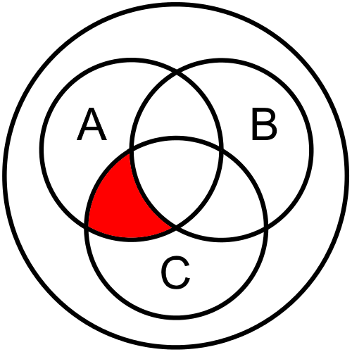
Let’s look at the first line where the output is True, which is the fourth line. In that line, we see that we need the part of the diagram that is contained in B and C, but not A. This is due to the fact that the inputs B and C are True, but input A is False on that line of the truth table. So, we’d shade in this segment of our Venn diagram:

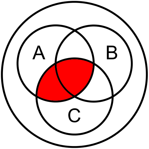
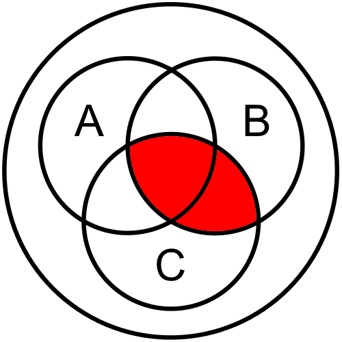
The next line in the truth table where the output is True is the sixth line. In this line, we need the part that contains A and C but not B:
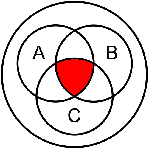
Finally, the last line in the truth table tells us that we must shade in the part of the diagram contained in all three circles, containing A and B and C together:
Now, we can put those sections together to find our overall Venn diagram for this statement:
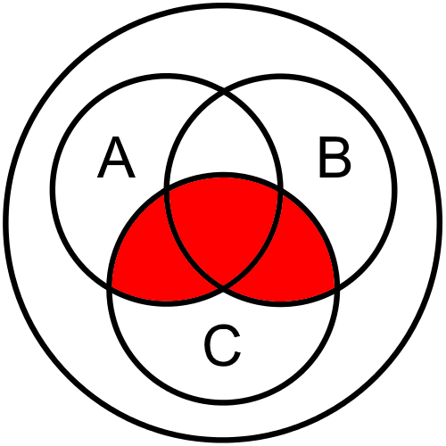
So, we can see that there are three segments shaded in our Venn diagram, corresponding to three lines in the truth table where the output is True. This gives us a helpful visual way to look at our Boolean logic expression.
Boolean Expression from Venn Diagram
Now that we’ve created a Venn diagram for this example, we can use it to create our Boolean expression. For this step, we’ll need to break the shaded part of the Venn diagram down into parts we can describe, and put those pieces together in a way that they represent the diagram as a whole. Let’s see how that works.
First, looking at our diagram, one thing we might notice is that it can be broken up into two overlapping segments. The first segment is this one:
This diagram shows the part of the diagram that is included in both A and C. This is exactly the same as the 2 variable Venn diagram we saw on the previous page, especially if we ignore the circle for B. So, this diagram represents the Boolean expression $ A \land C $. That’s one piece of the puzzle.
The other segment we might see is this one:
Similarly, this diagram represents the Boolean expression $ B \land C $, since it is the part of the diagram that is included in both B and C.
If we overlap those two segments, we would see the following result (with overlapping segments shaded a bit darker):
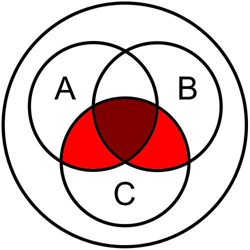
This is effectively the same diagram as we found above, isn’t it? That’s what we are aiming for!
So, we know that we need an expression that represents $ A \land C $ and $ B \land C $ overlapped. If we recall back to the basic Boolean operations, we should hopefully remember that the or operation does just that. So, we can use $ \lor $ to connect our two pieces, making the final Boolean expression:
$ (A \land C) \lor (B \land C) $Now that we have our final expression, let’s go back to the problem statement and see if it matches. Recall that it says we would like the lights turned on if the light switch is on and the master switch is on, or if the motion sensor senses people and the master switch is on. If we replace the variables in the Boolean expression, we see the following:
$ (\text{Light Switch} \land \text{Master Switch}) \lor (\text{Motion Sensor} \land \text{Master Switch}) $That is exactly what we want! So, we found the correct Boolean expression for our problem statement.
Of course, once you’ve seen the end result and compared it to the problem statement, it may be easy to see how you could quickly go directly from the problem statement to a Boolean expression without creating a truth table or a Venn diagram. In fact, if the problem statement is clear enough, it may already be structured exactly like a Boolean expression itself.
In practice, many programmers become familiar enough with Boolean expressions that they can easily go directly from a problem statement to a matching Boolean expression without much effort. It may seem difficult at first, but you’ll quickly become familiar with that process as you continue to write programs. For now, don’t be afraid to take the time and work each example through until you become more comfortable with it.
It usually takes at least a year or more of coding practice before this process feels simple. So, don’t sweat it!
Boolean Expression from Truth Table
We can also derive our Boolean expression directly from the data in the truth table, along with some of the Boolean Algebra laws we covered earlier in this chapter. Let’s go through an example of how that process works, just to see that we can get the same result.
In our truth table, we see that we should have three situations that provide output. The first is when B and C are True, while A is False. So, we could write that as the Boolean expression
$ \neg A \land B \land C $.
Similarly, we can do the same for the other two lines of output, which produce the expressions $ A \land \neg B \land C $ and $ A \land B \land C $, respectively.
Finally, we’d like our output to be True if at least one of those situations is True. So, we can use the or
$ \lor $ operation to connect them together into a single statement:
In fact, if we want, we can simply stop there. That statement is exactly equivalent to the one we found using the Venn diagrams above.
Further “Simplification”
However, it is very long and difficult to understand directly, and it doesn’t clearly reflect our problem statement. So, let’s see if we can reduce this expression using the laws of Boolean Algebra to an equivalent one that is easier to read.
First, we must use the law of Idempotence to duplicate one of our terms. From that law, we know that the following is true:
$ (A \land B \land C) \iff (A \land B \land C) \lor (A \land B \land C) $So, we can replace the final term with this equivalent statement. We can do this here since it won’t affect the final outcome. It is the rough equivalent to adding $ 0 $ to an existing mathematical expression. So, our new expression is
$ (\neg A \land B \land C) \lor (A \land \neg B \land C) \lor (A \land B \land C) \lor (A \land B \land C) $Next, we can use the law of Commutativity to rearrange the terms a bit. This is the same as rewriting $ 1 + 2 $ as $ 2 + 1 $, so it is a simple law to apply:
$ (\neg A \land B \land C) \lor (A \land B \land C) \lor (\neg B \land A \land C) \lor (B \land A \land C) $We can also use the law of Associativity to add a few extra parentheses, just for clarity:
$ \bigg(\big(\neg A \land (B \land C)\big) \lor \big(A \land (B \land C)\big)\bigg) \lor \bigg(\big(\neg B \land (A \land C)\big) \lor \big(B \land (A \land C)\big)\bigg) $Next, we can apply the inverse of the Distributive law on the first block of statements to “factor out” the statement $ (B \land C) $, leaving this result:
$ \big((B \land C) \land (\neg A \lor A) \big) \lor \bigg(\big(\neg B \land (A \land C)\big) \lor \big(B \land (A \land C)\big)\bigg) $We can also do the same on the second block with $ (A \land C) $:
$ \big((B \land C) \land (\neg A \lor A) \big) \lor \big((A \land C) \land (\neg B \lor B)\big) $Next, we can use the Complement law to reduce both
$ (\neg A \lor A) $ and
$ (\neg B \lor B) $ to True:
Then, using the law of Identity, we know that $ x \land T \iff x $, so we can remove both instances of $ T $ in the expression:
$ (B \land C) \lor (A \land C) $Once again, we can apply the law of Commutativity to rearrange the terms to reach this final result:
$ (A \land C) \lor (B \land C) $There it is! We were able to use the laws of Boolean Algebra to prove that our Boolean expression found using the Venn diagrams is equivalent to the expression from the truth table. This process is very similar to the ones learned in an algebra class, but some of the laws are handled in a slightly different way.
Here’s a quick challenge: can you use the laws of Boolean Algebra to reduce that statement even more? See if you can find the answer before reading below.
It turns out that you can! We can apply the inverse of the Distributive law one more time to get the following result:
$ C \land (A \lor B) $
This also works, and might even fit better with the original problem statement. If we restate it as “the light should be on if the master switch is on and either the light switch is on or the motion sensor detects people,” the problem statement clearly reflects this answer as well. Both are equally correct in this case.